Tech Log #034: Milling v0.1 sensor node
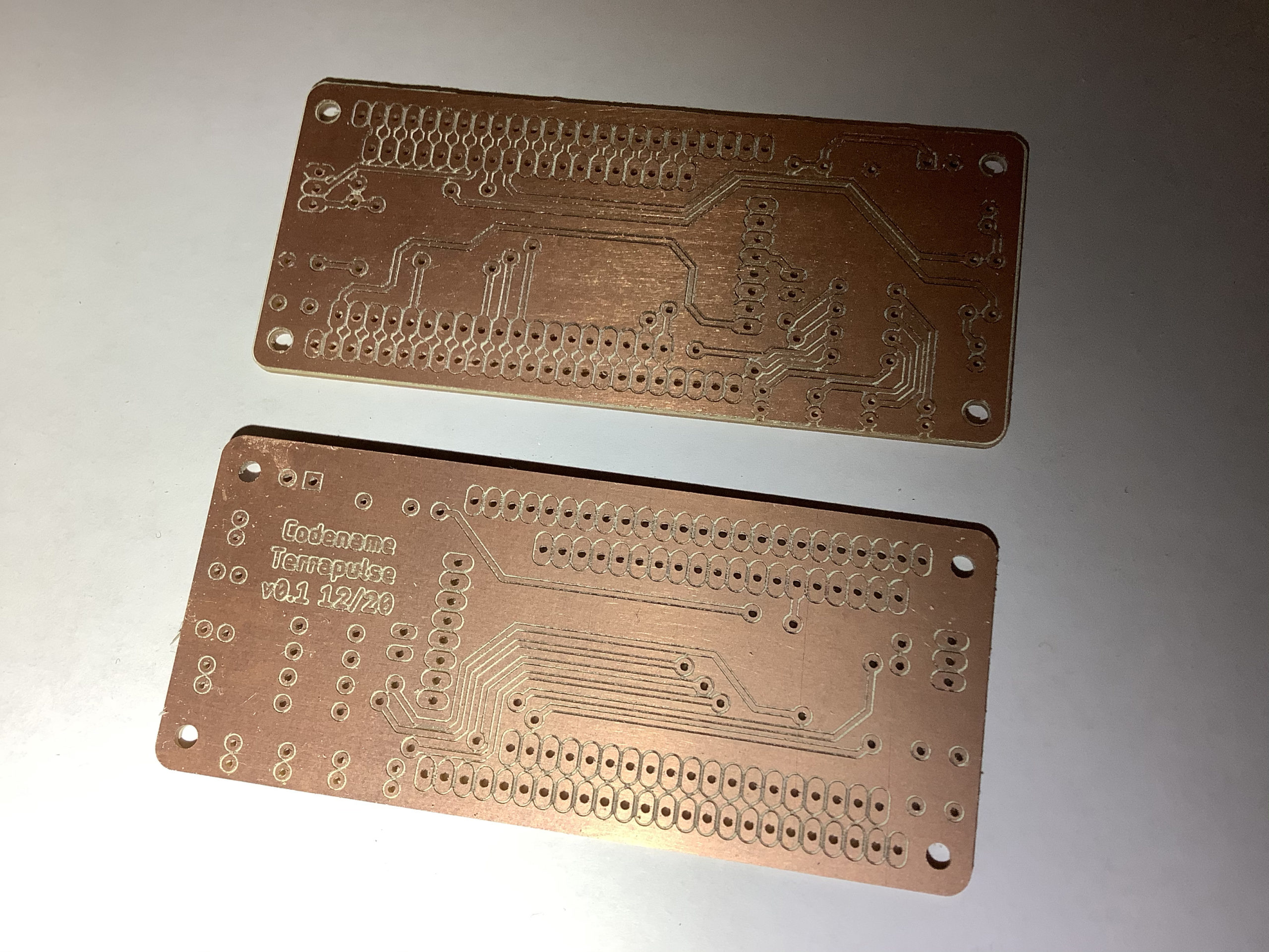
Milled the board, it’s done! Two of them actually – in case one of them failed. It was a long milling operation, taking up the entire space of the 4×6″ double sided copper clad piece. A 0.005″ v bit was used for engraving the traces, and a 1/32″ bit for the drills and outline. Decided to drill the holes on both sides (before flipping and after) and it helped to reduce the amount of time afterwards in post-processing by poking out some of the pieces that didn’t go through all the way. So that’s a great help. The thermal pads for the Gnd copper pour turned out well.
There were two mistakes found out on this iteration: forgot the resistor for the speaker, so this was wired in by hand after. White LED 1 on IO0 has the via going to the top layer through the pin pad. This doesn’t work since the holes are not through-plated. The solution was to jumper from the extra pad to the via, and the problem was solved. Hooray, the extra row of pads comes in useful for prototyping! Next step is coding more of the blinking patterns.
-
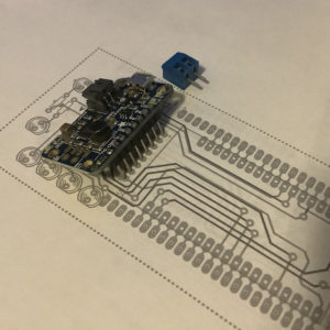
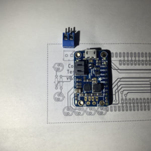
- Paper test 1
-
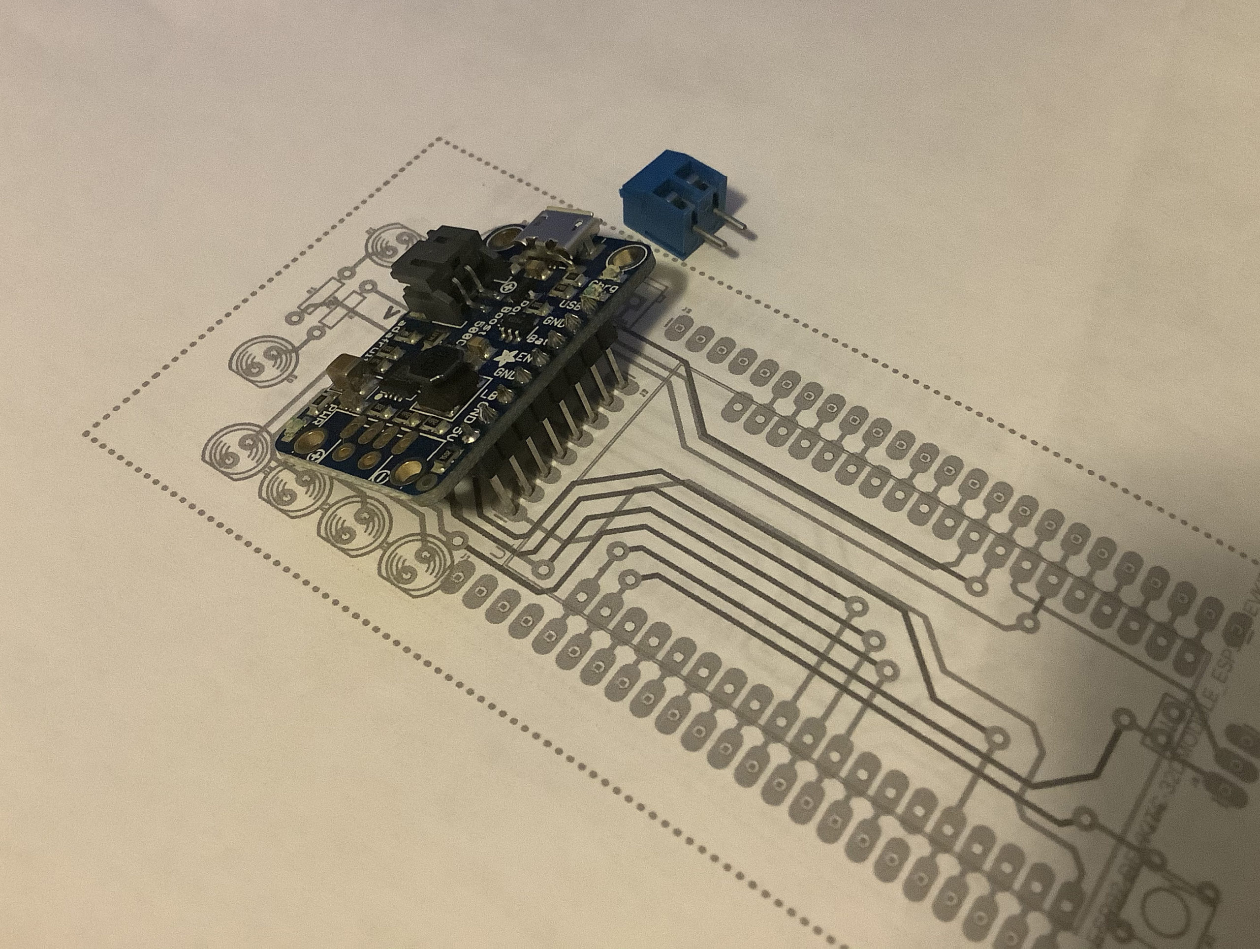
- Paper test 2 after some adjustments
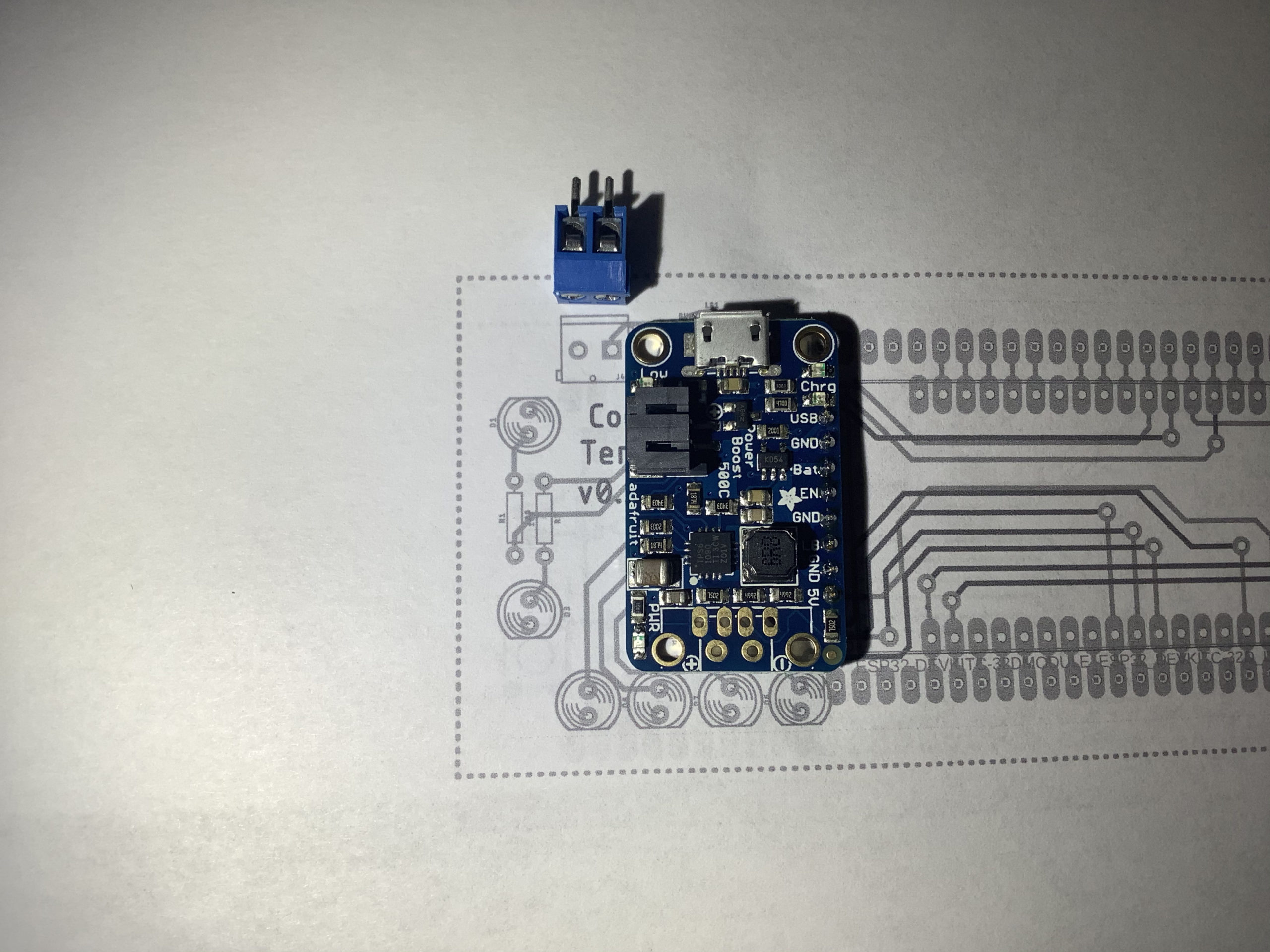
-
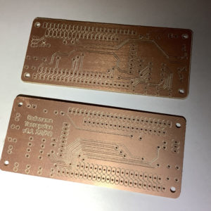
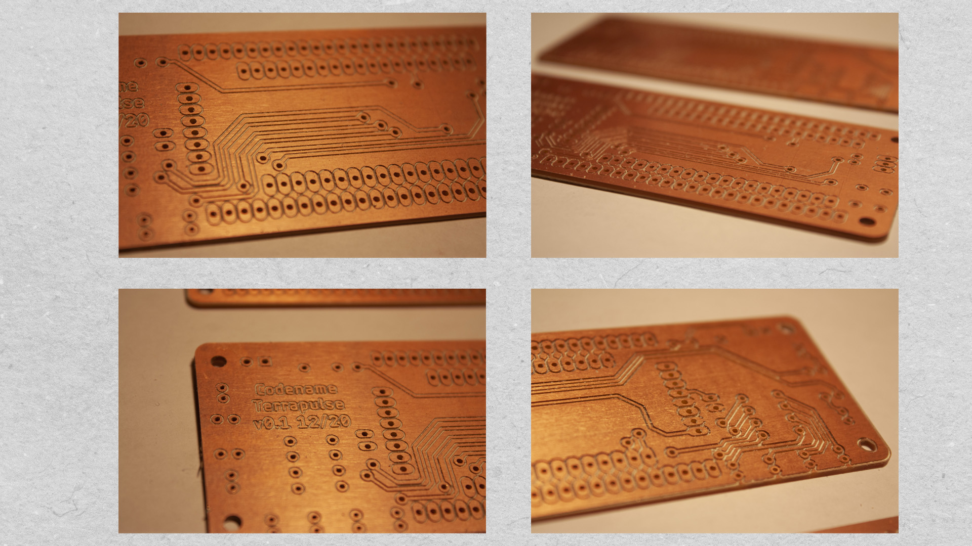
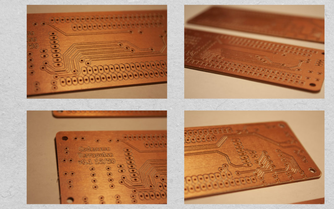
- Boards milled
-
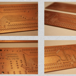
- Closeup of boards