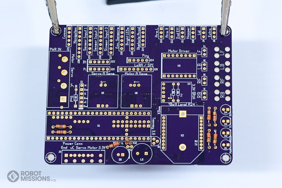
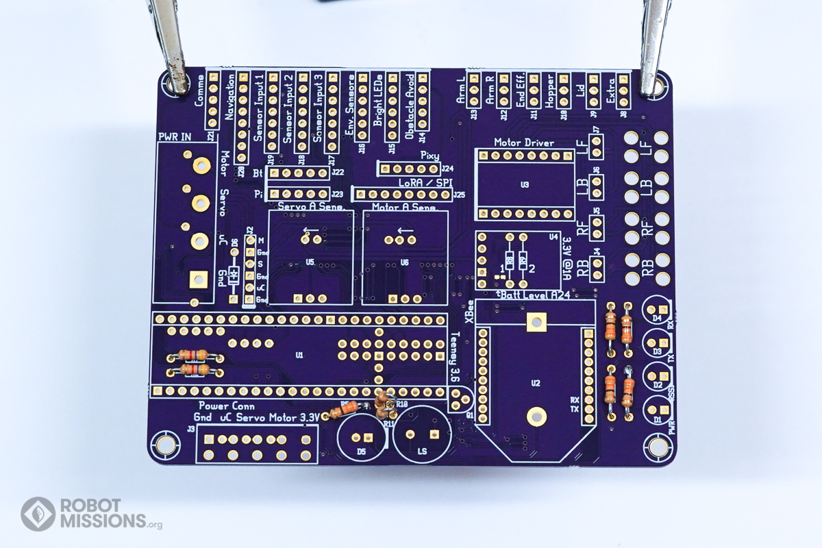
In this first section, we are going to warm up our soldering skills by soldering the resistors and diodes first. In this section you will need the 6x 330 ohm resistors, the 2.0K ohm resistor, the 2x 4.7K ohm resistors, and the 1N4001 diode.
Take the 330 ohm resistors and insert them into R1, R2, R3, R4, R5 and R10.
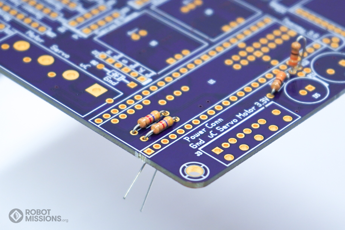
Here are the resistors inserted in R1, R2, R3, and R4.
Here are the resistors inserted in R5 and R10. Make sure the leads of both resistors are not touching.
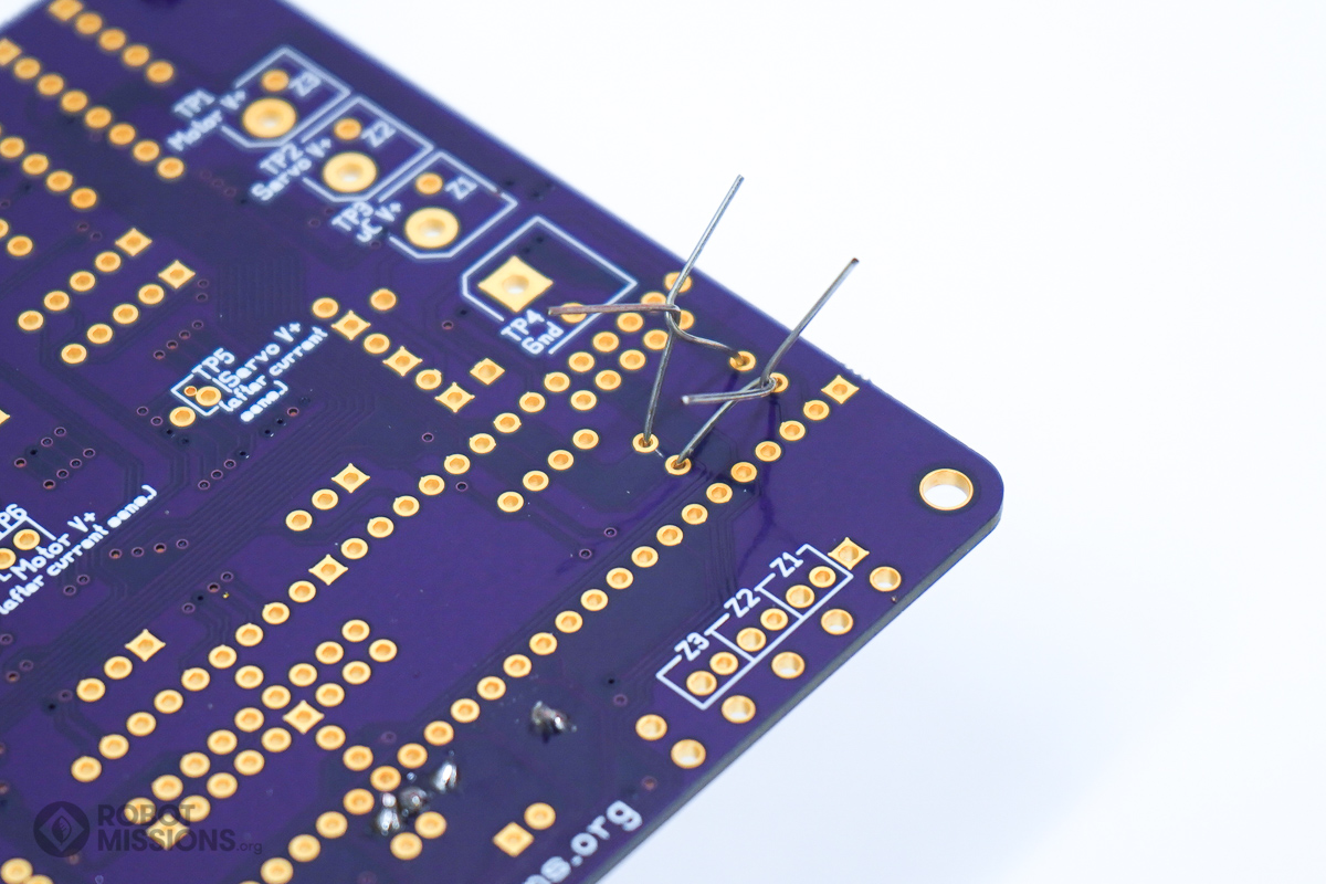
Twist the leads of the resistors together. Then, flip the board over.
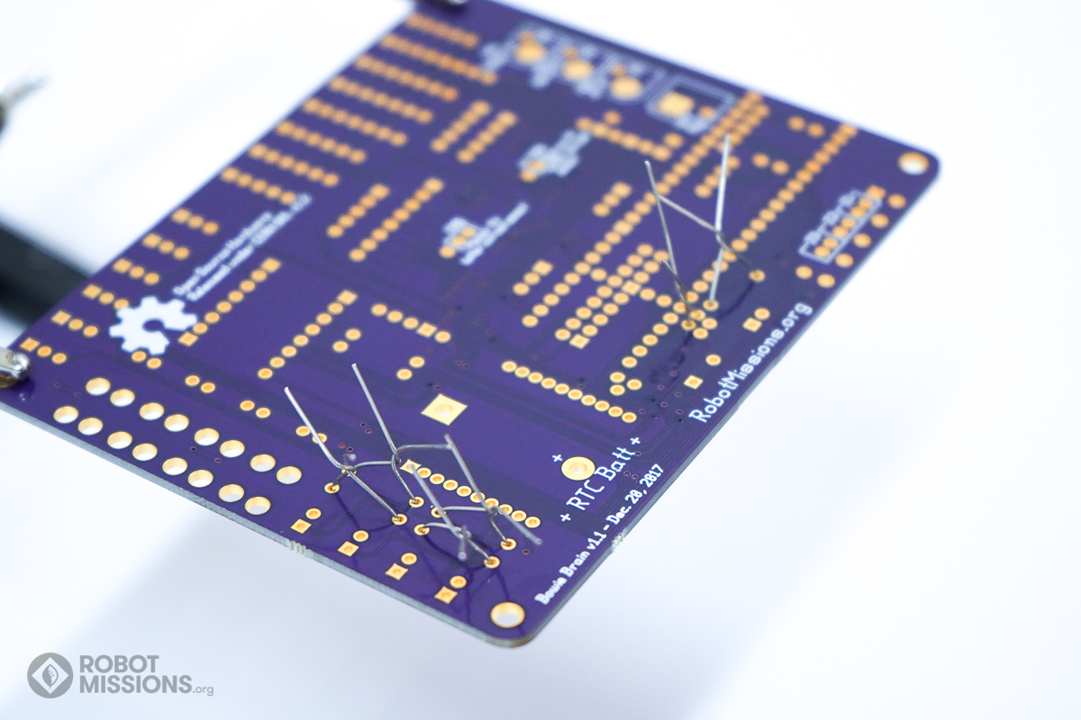
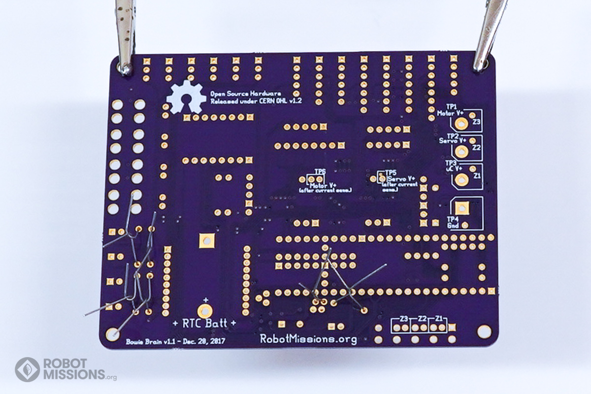
This is what the leads look like on the back of the board. Ensure that the components are still flush with the top side of the board, as it may have moved during flipping.
Solder the pads with your soldering iron and solder. Then, cut the leads using diagonal cutters. Once complete, flip the board over.
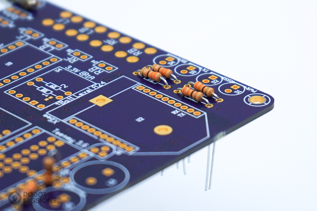
Now insert the two 4.7K ohm resistors in R6 and R7.
These are used as pull-up resistors for the i2c on the Teensy.
These are used as pull-up resistors for the i2c on the Teensy.
Here are the resistors inserted into R6 and R7.
Twist the leads of the resistors together. Then, flip the board over.
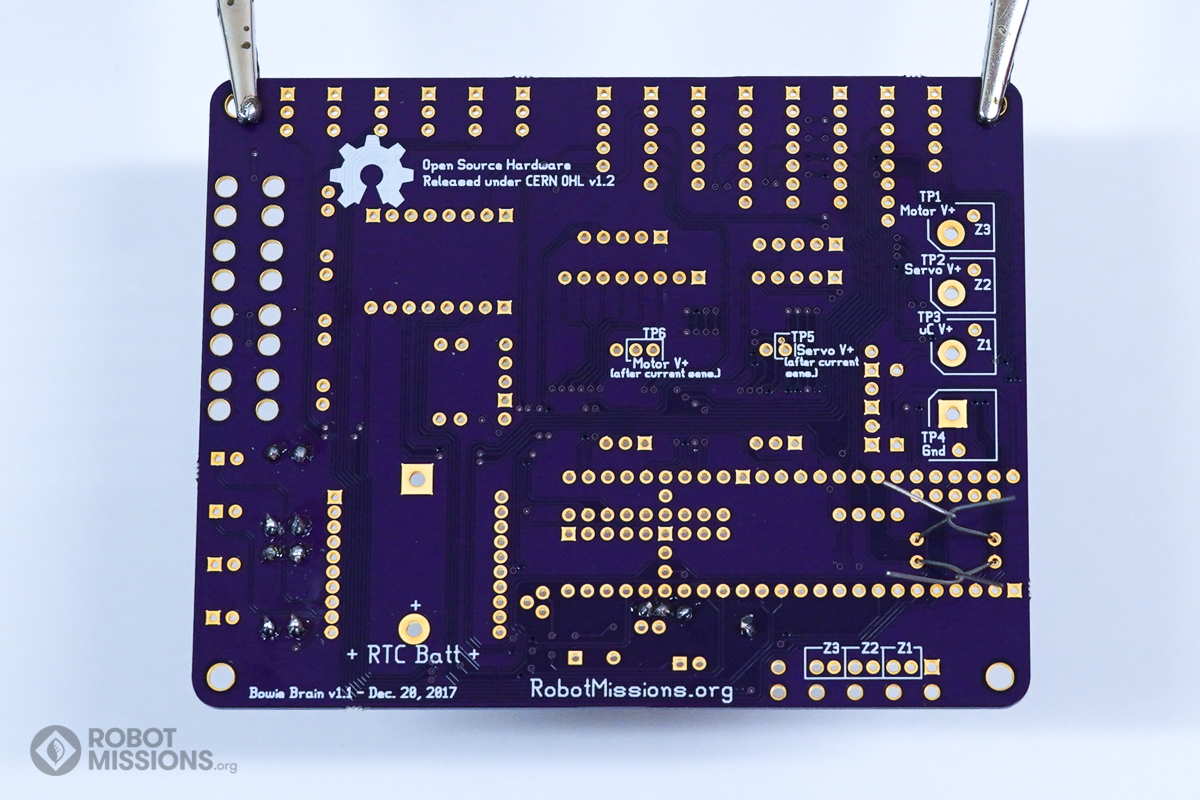
This is what the leads look like on the back of the board. Ensure that the components are still flush with the top side of the board, as it may have moved slightly during flipping.
Solder the pads with your soldering iron and solder. Then, cut the leads using diagonal cutters. Once complete, flip the board over.
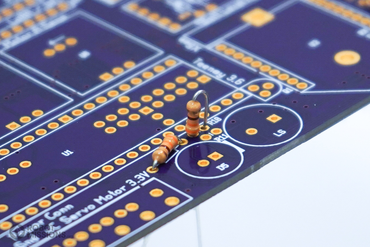
Insert the 2.0K ohm resistor into R11.
This is used for the speaker circuit.
This is used for the speaker circuit.
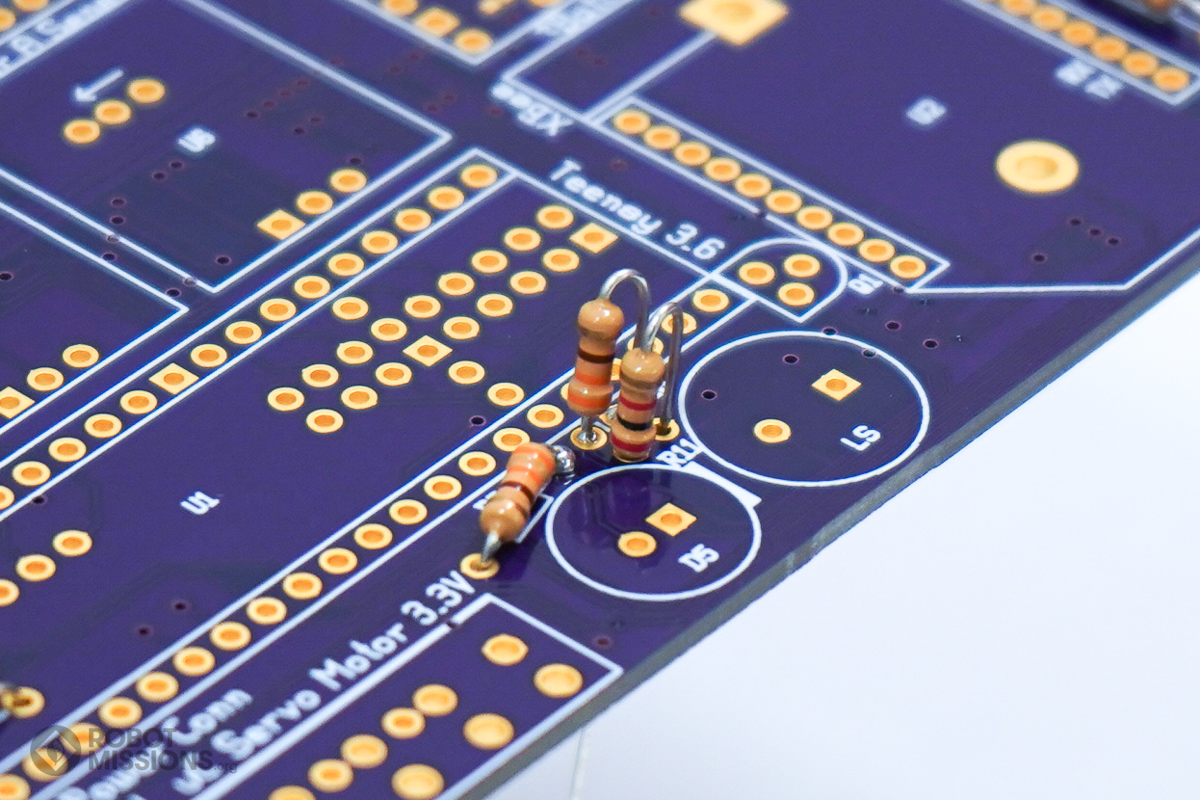
Here are the resistors inserted into R10 and R11.
Twist the leads of the resistors together. Then, flip the board over.
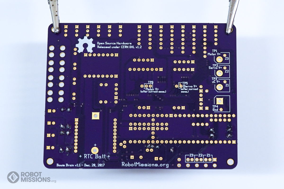
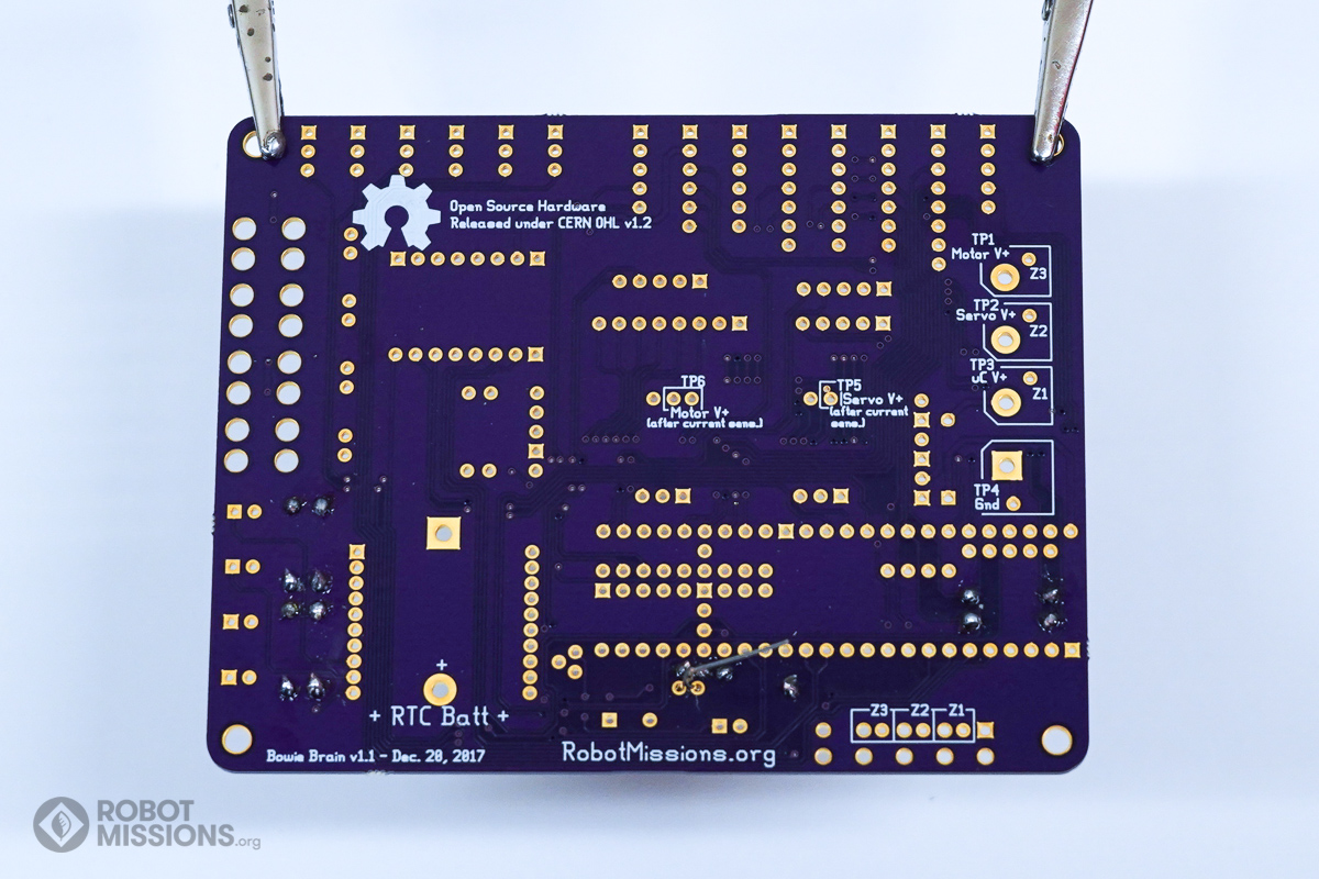
This is what the leads look like on the back of the board. Ensure that the components are still flush with the top side of the board, as it may have moved slightly during flipping.
This is what the leads look like on the back of the board. Ensure that the components are still flush with the top side of the board, as it may have moved slightly during flipping.
Solder the pads with your soldering iron and solder. Then, cut the leads using diagonal cutters. Once complete, flip the board over.
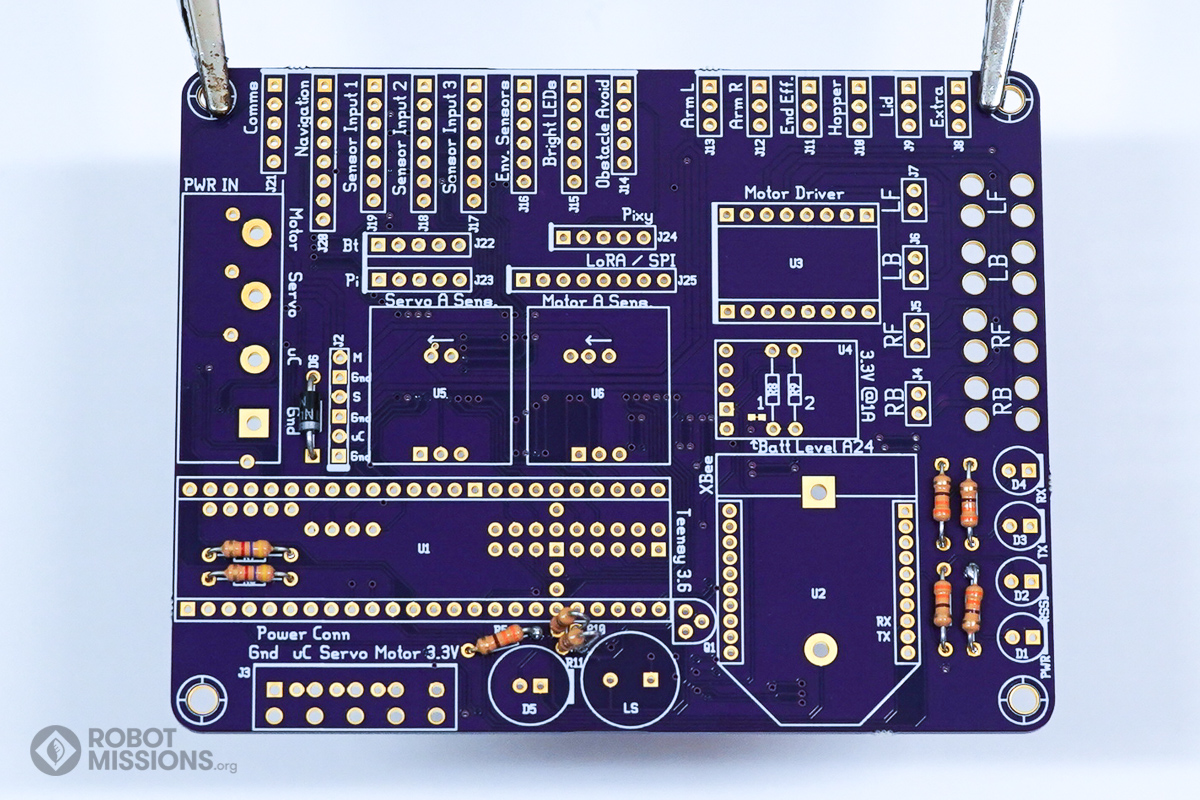
Insert the diode into D6. The silver line on the diode should match the line on the circuit board. This diode is used to prevent reverse polarity, and to prevent the USB voltage from going back in to the power supply.
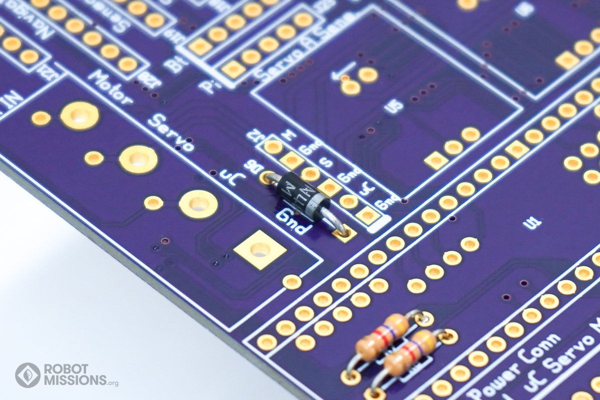
Here is the diode inserted in to D6. Notice how the two lines match up.
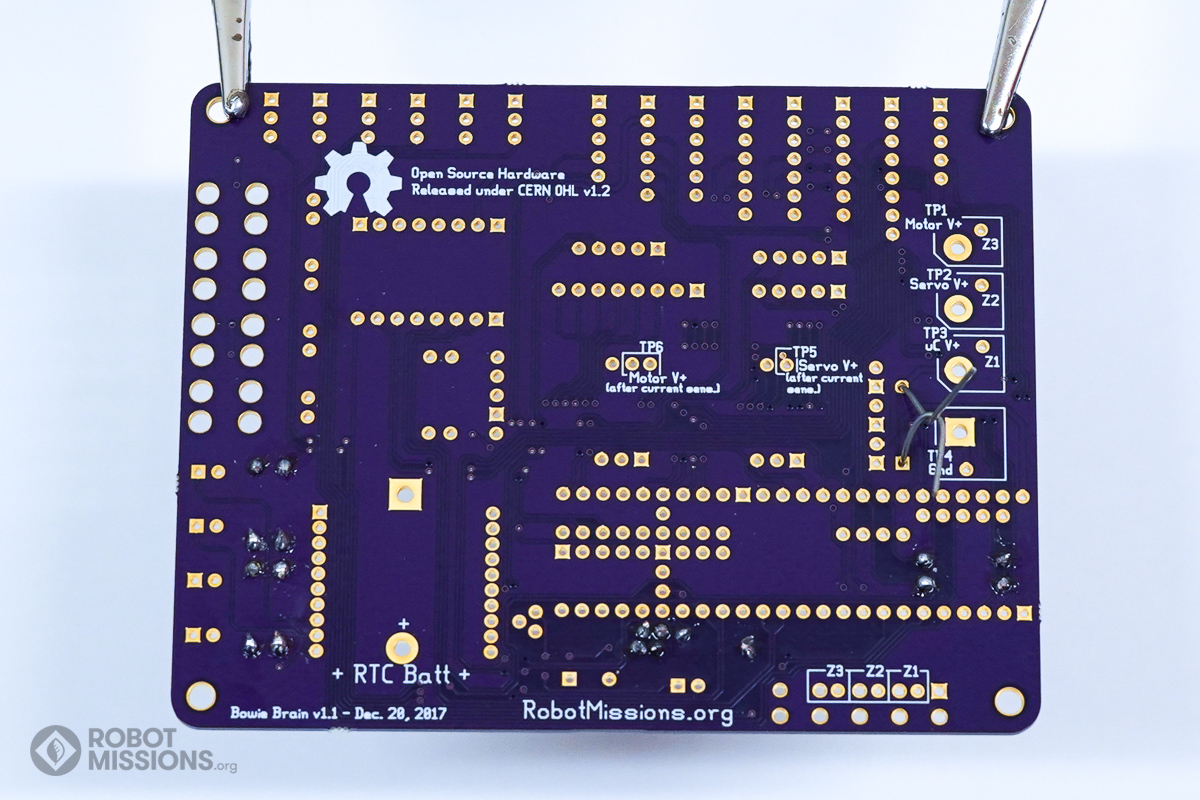
Twist the leads of the diode together. Then, flip the board over.
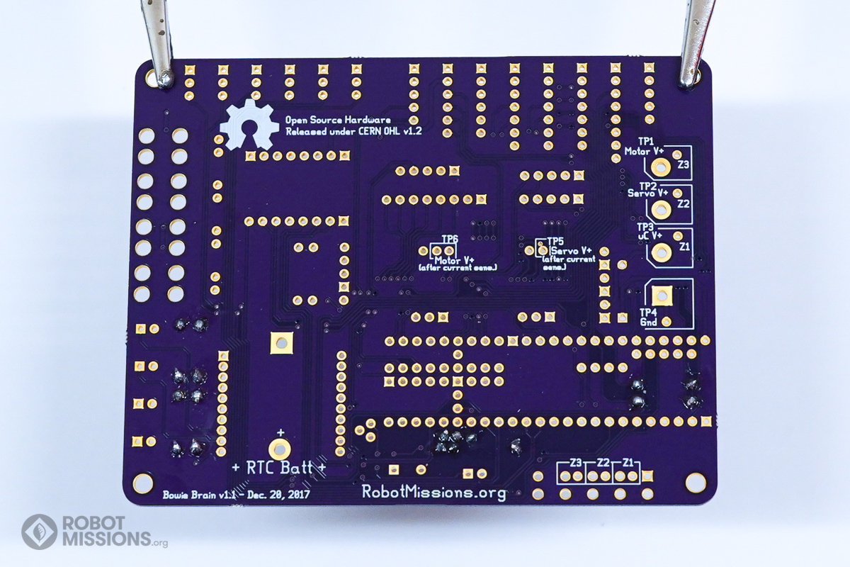
This is what the leads look like on the back of the board. Ensure that the components are still flush with the top side of the board, as it may have moved slightly during flipping.
This is what the leads look like on the back of the board. Ensure that the components are still flush with the top side of the board, as it may have moved slightly during flipping.
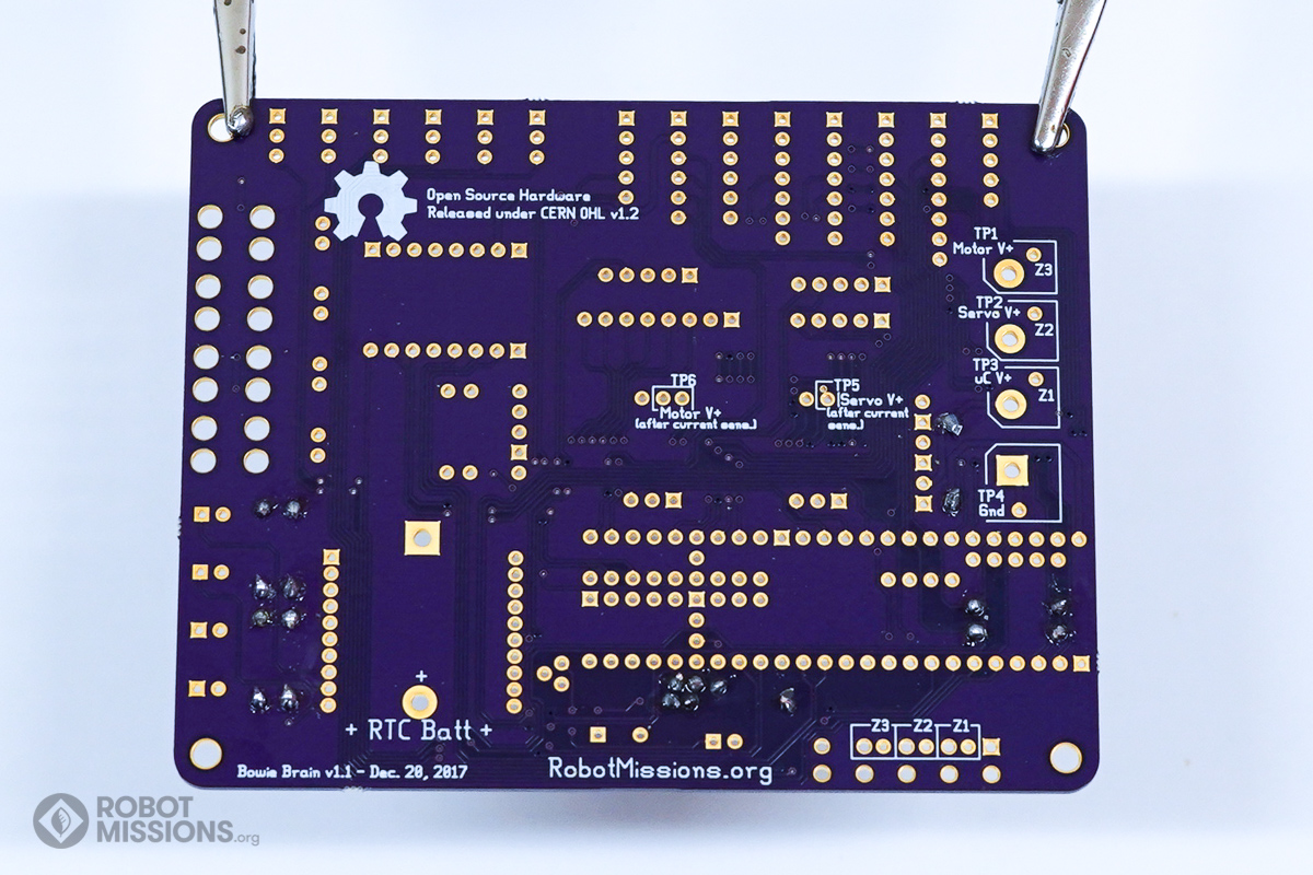
Solder the pads with your soldering iron and solder. Then, cut the leads using diagonal cutters. Once complete, flip the board over.
| ← Introduction | LEDs galore, and one speaker → |