by Erin RobotGrrl | Dec 29, 2019 | News, Progress Logs
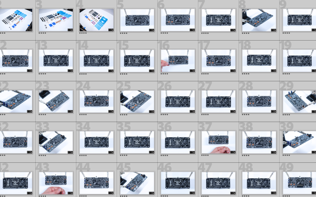
Today some progress was made on editing the operator interface kit photos. Of the 187 that need to be edited, 59 are complete. Although it’s small progress, it is still making progress.
Next kit log will continue on this, as well as the motor kit photos.
by Erin RobotGrrl | Dec 28, 2019 | News, Progress Logs
Today’s progress was making a small dent in the mountain of photos to edit. The process involves importing, looking at each one, and flagging the best ones (most in focus, clear, shows what is happening). Here’s a look at it number wise:
Super bright lights is 570 photos total, with 108 of them to be edited. Editing = done.
Operator interface is 750 photos total, with 187 of them to be edited. Editing = started, but not done (need to crop and double check colour correction).
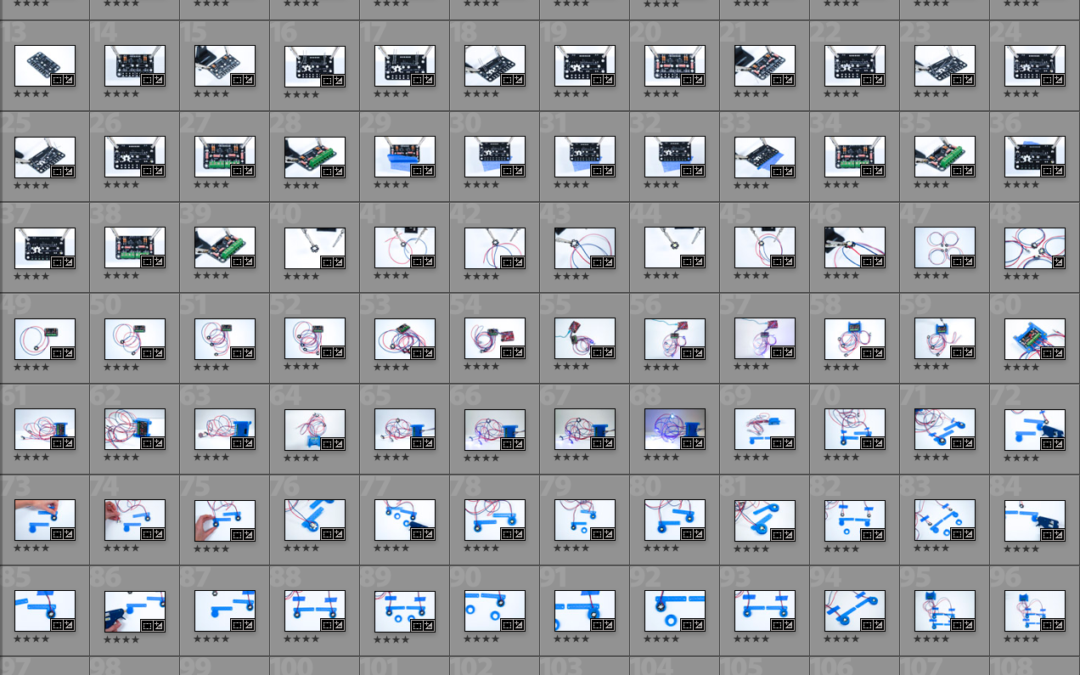
Wheel kit is 440 photos total, with 91 of them to be edited. Editing = not started.
The next kit log will continue this progress on the photos.
by Erin RobotGrrl | Dec 24, 2019 | News, Progress Logs
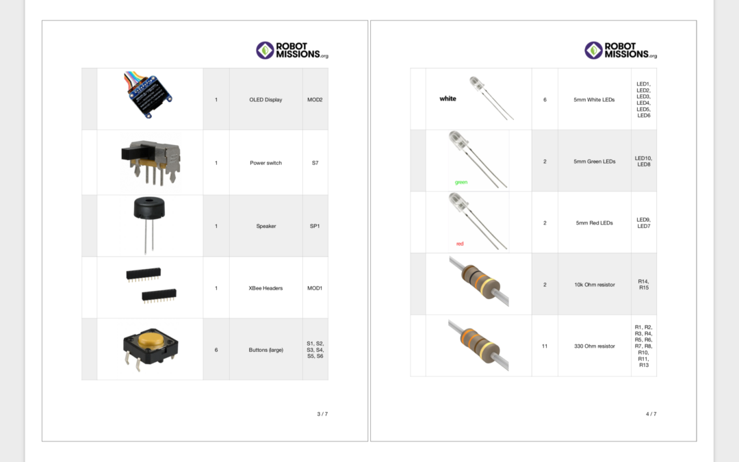
Today we completed the operator interface kit packing list. Luckily we had already made some progress on it prior, when we were assembling the kit and taking photos. It was previously listed at step 0.5, but now that the packing list is done it jumps to step 3, which is organising and editing the photos.
Yesterday we mentioned that the power pack kit was at step 2.5, but it’s actually at step 4. The reason for this is because initially we though the packing list was not done, but indeed – it was already done.
The next step will be to make the packing list for the super bright lights kit, and edit the photos for the operator interface kit. At some point we will need to revisit writing the words for the power pack kit instructions.
by Erin RobotGrrl | Dec 18, 2019 | News, Progress Logs
Yesterday the kit log was partially in progress while finishing the operator interface assembly. That is now complete. The steps that followed were finishing the keypad with soldering the buttons, resistors, leds, and of course the joystick. Next was adding the boards to the enclosure, and adding the lids to them. Then taking photos of the finished product.
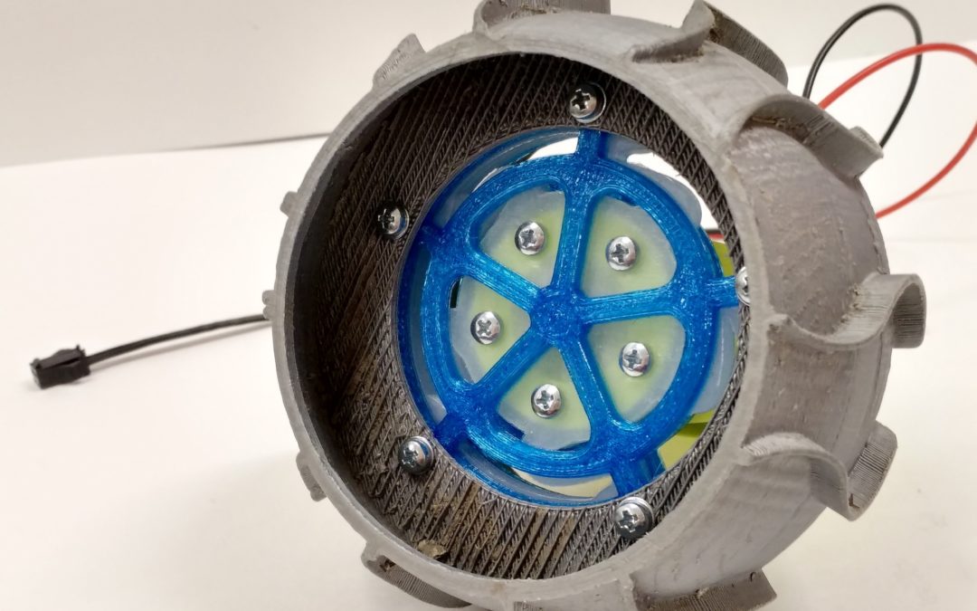
The kit to complete today was the wheel assembly. Although this one is documented through CAD images, some of the manoeuvres to do assembly can be tricky to see in that format. Additionally, the connector that goes from the motor terminals to the bowie brain should be attached in a certain orientation to ensure smooth changeover between different drive systems. For example, not flipping the wire polarity to cause the robot to go backwards when going forwards.
In the guide, we will have to mention to use JB weld on the hub and shaft. As well as blue threadlock on the set screw. Tonight, these were not added, because we wish to do all 4 in uniform. This means likely needing to disassemble the wheel in the future. However, that might be useful for a video.
Here’s a look at the assembly process:
-
-
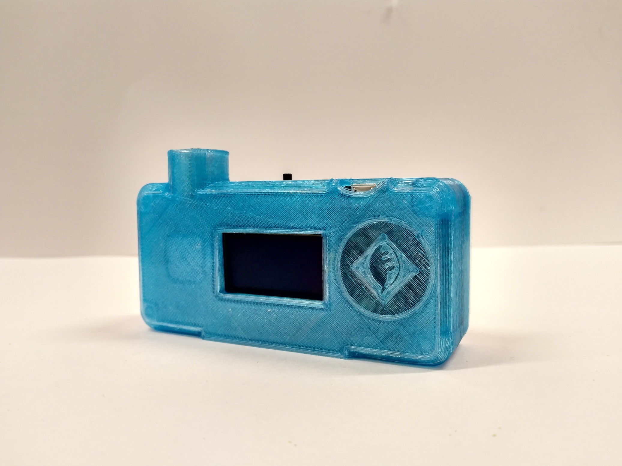
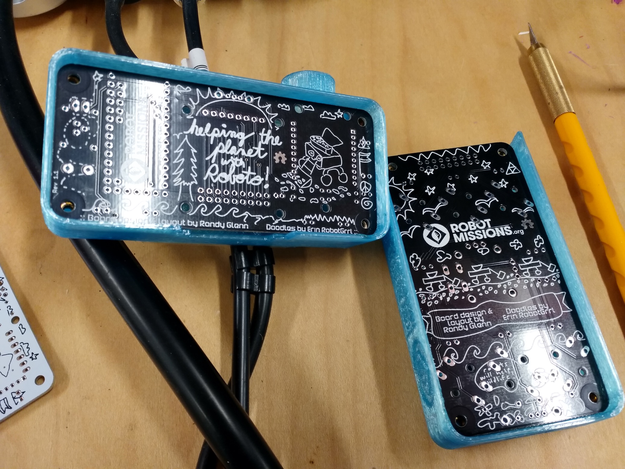
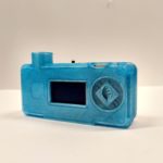
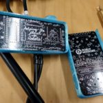
Operator interface display in its enclosure
-
-
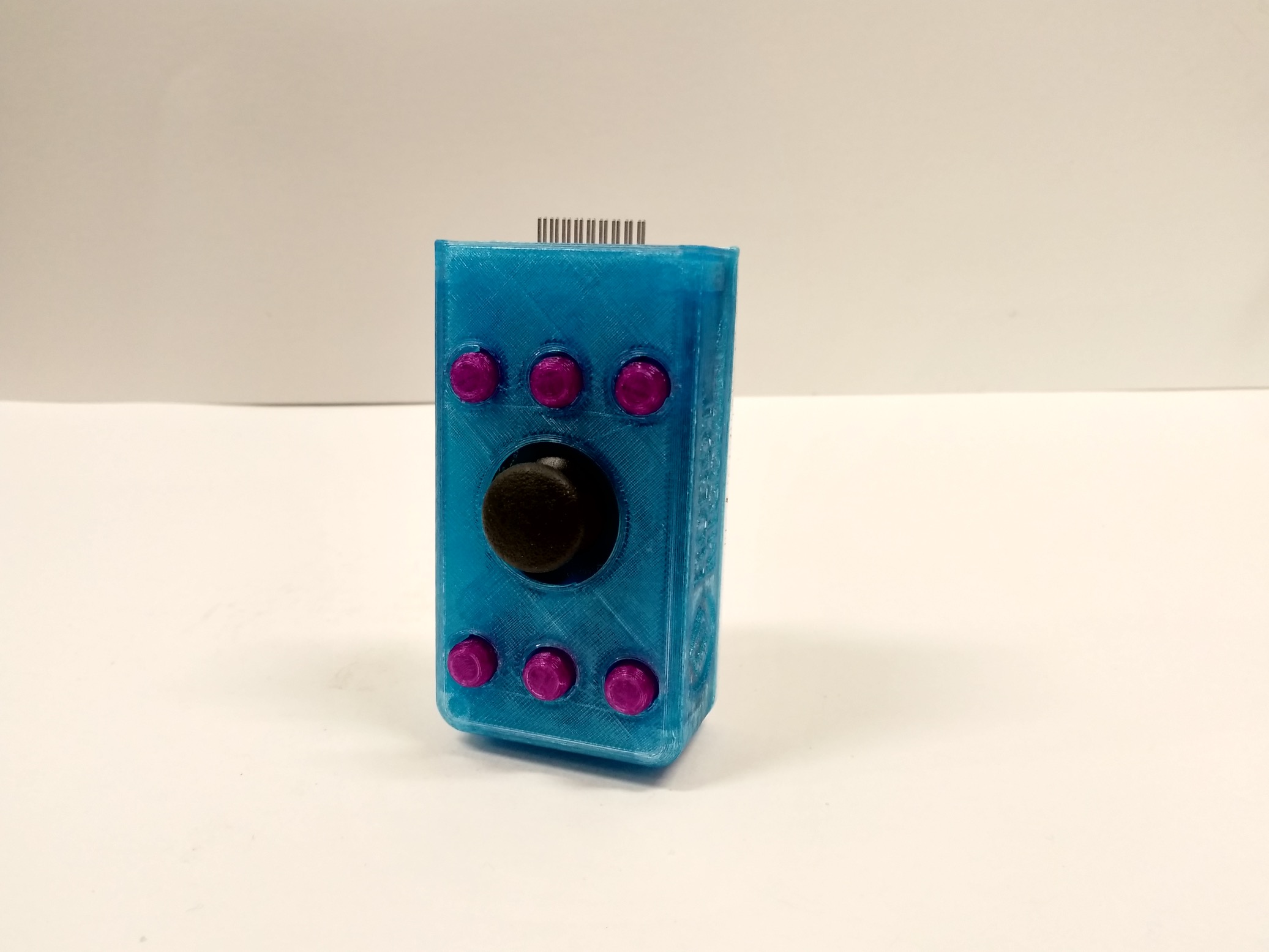
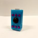
Operator interface keypad in its enclosure
-
-
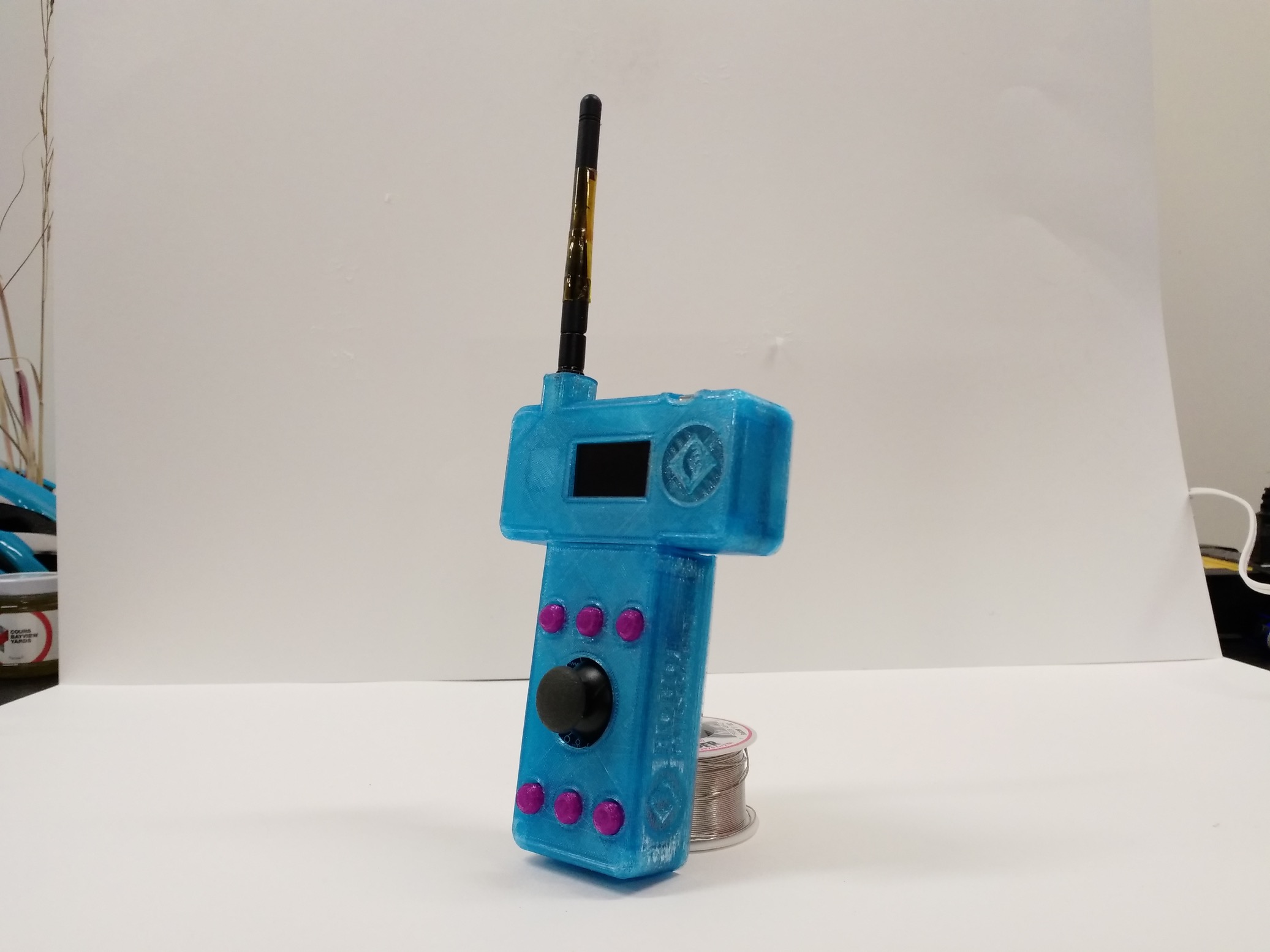
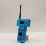
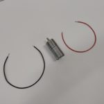
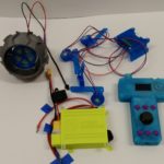
Both parts connected, antenna added
-
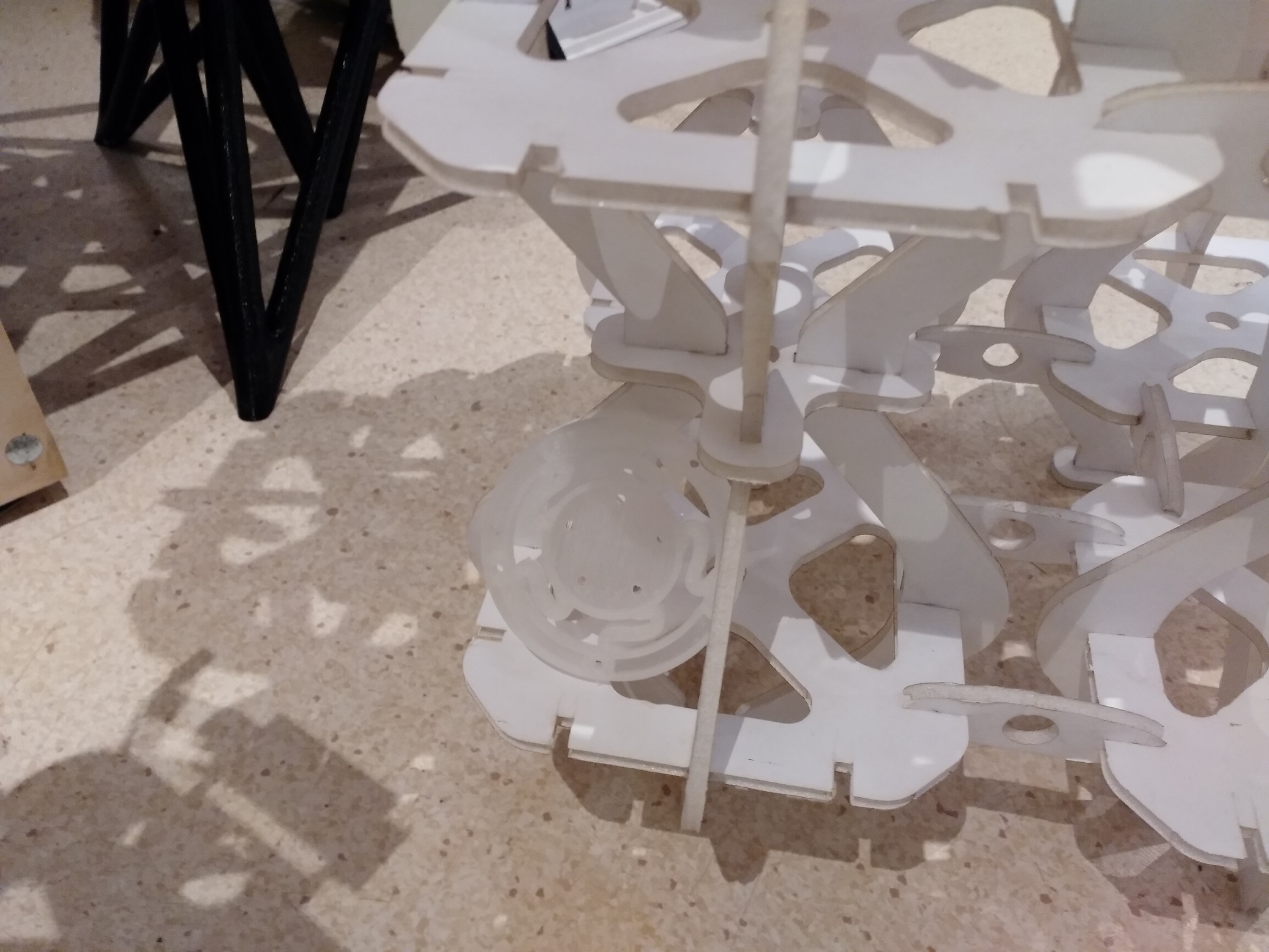
-
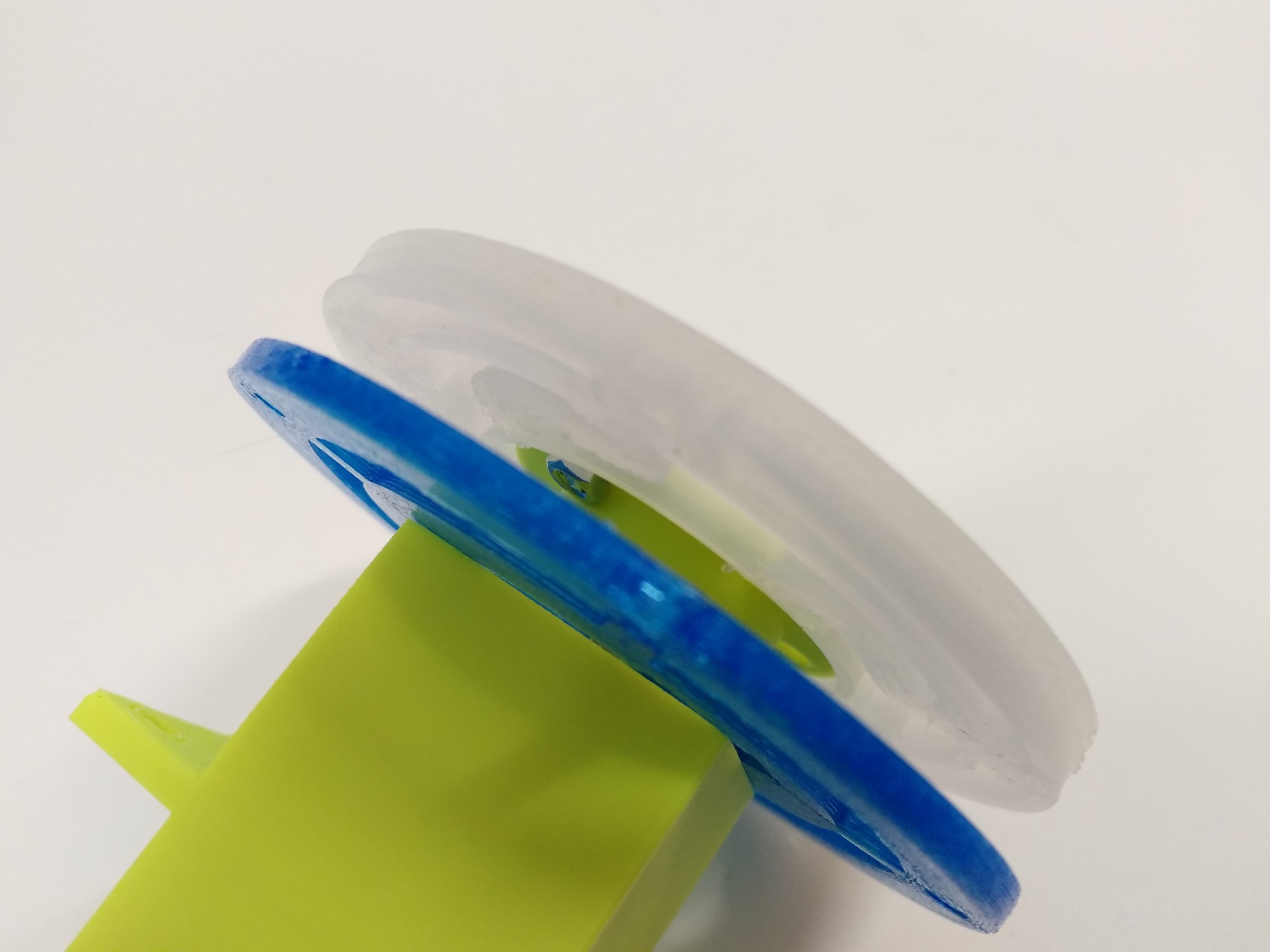
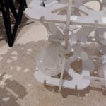
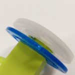
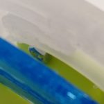
Couldn’t find the flexidisk, it was blending in well
-
-
Here it is!
-
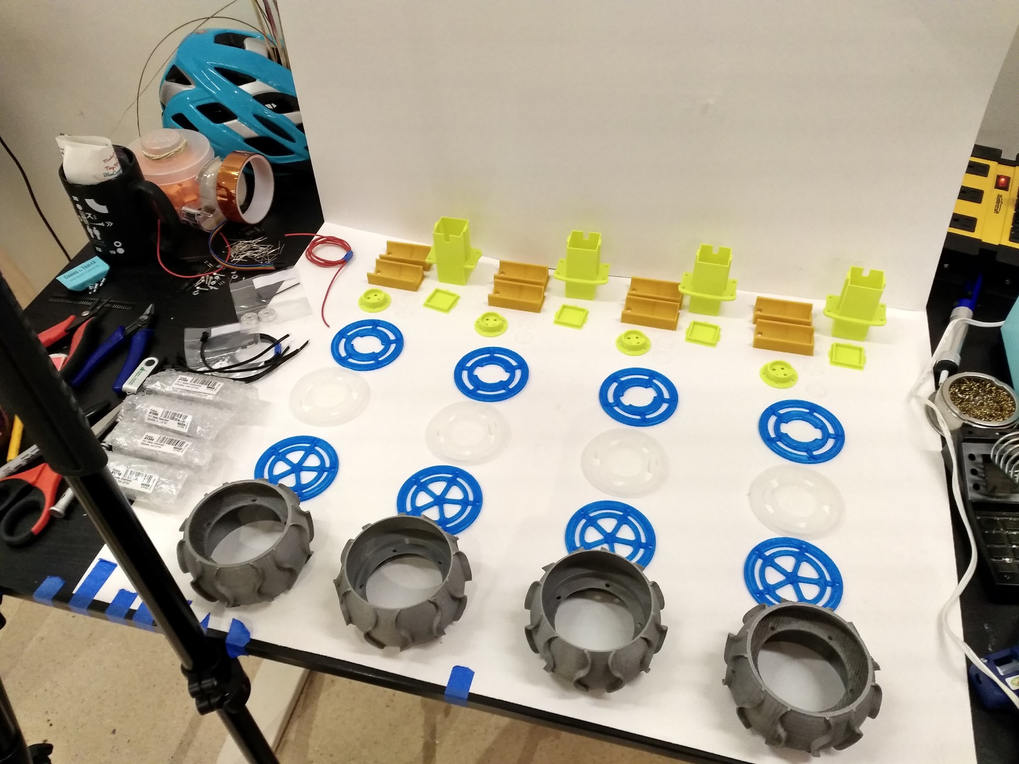
-
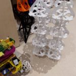
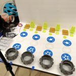
Was trying to capture all 4 wheels components at once, but there were too many for the size
-
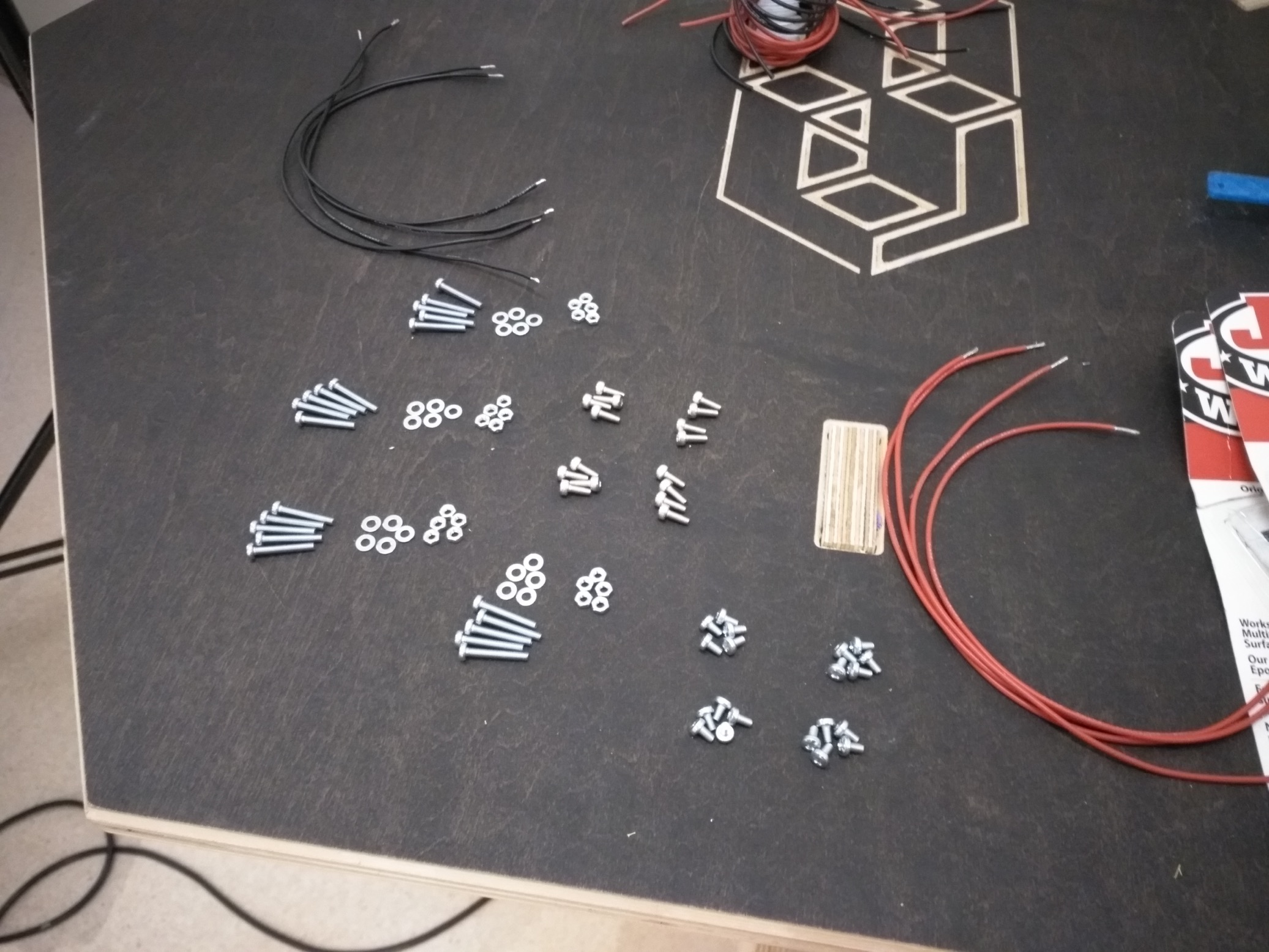
-
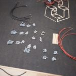
All the fasteners for the 4 wheels. However, 5 nuts * 4 are missing.
-
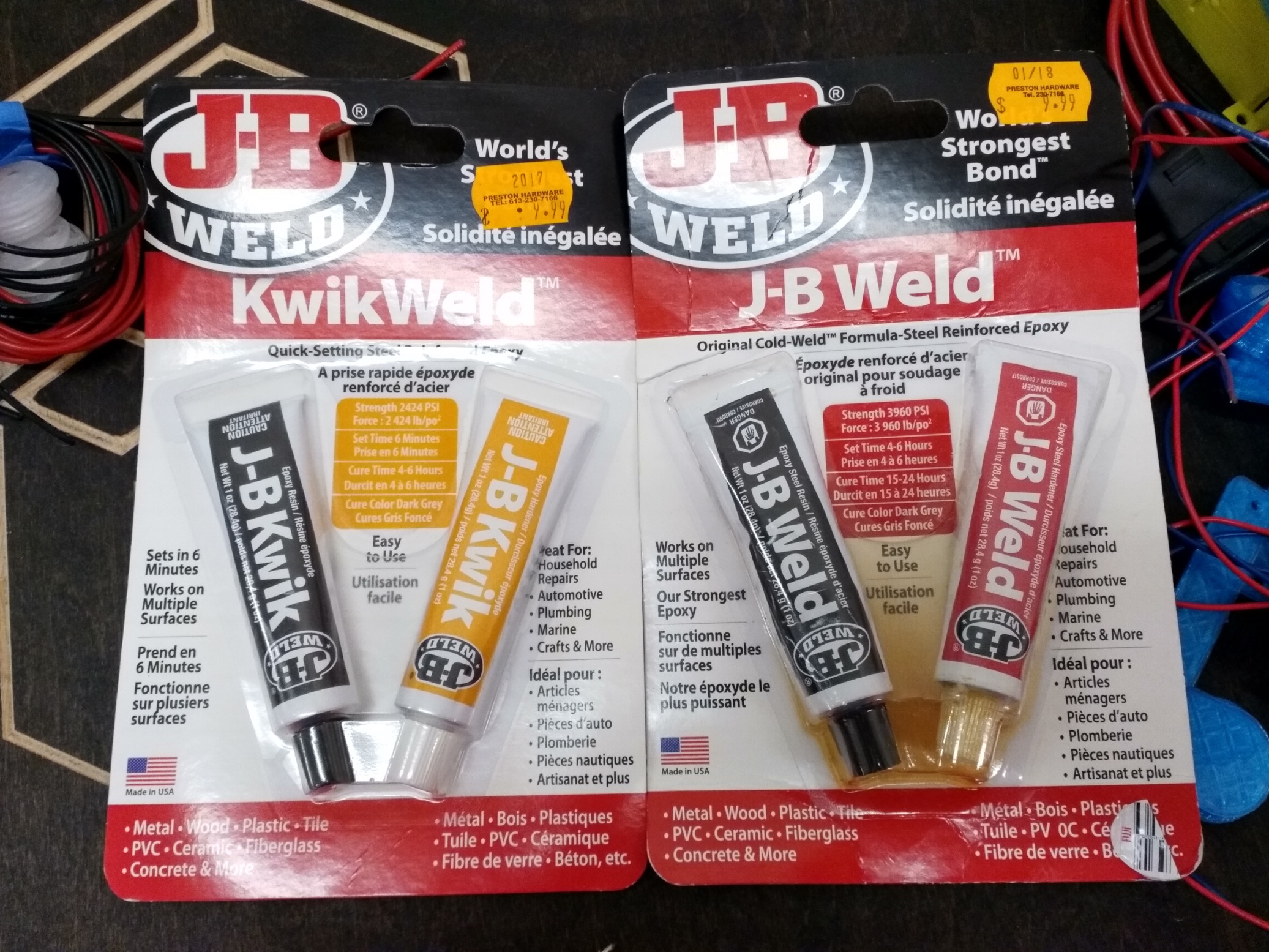
-
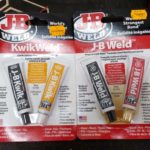
This is the adhesive that is used to permanently attach the hub to the motor shaft
-
-
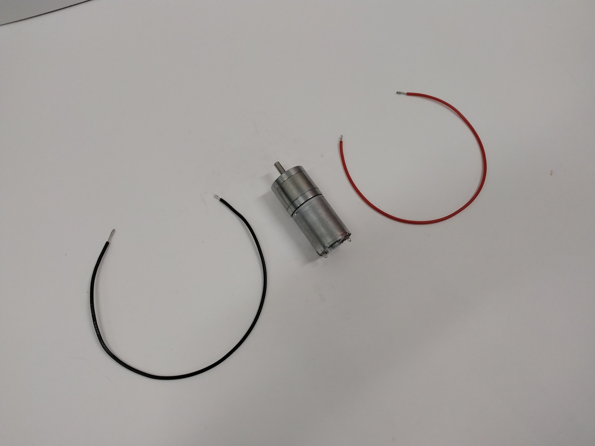
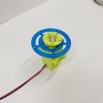
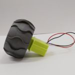
Motor, be ready to become a wheel!
-
-
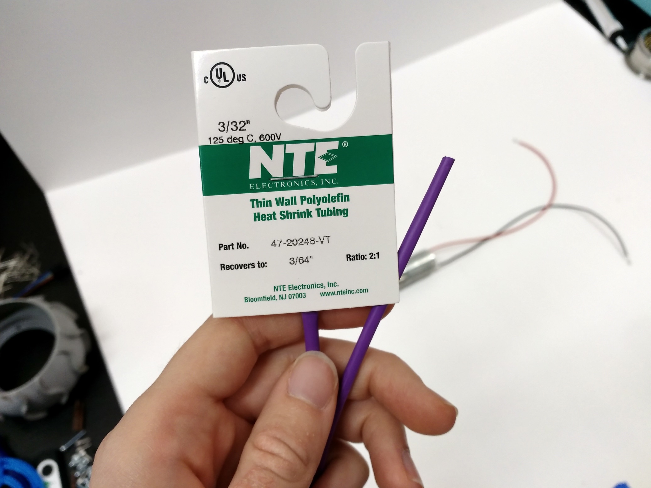
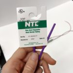
This diameter of heatshrink is very useful for the common hobby gauge wires
-

-
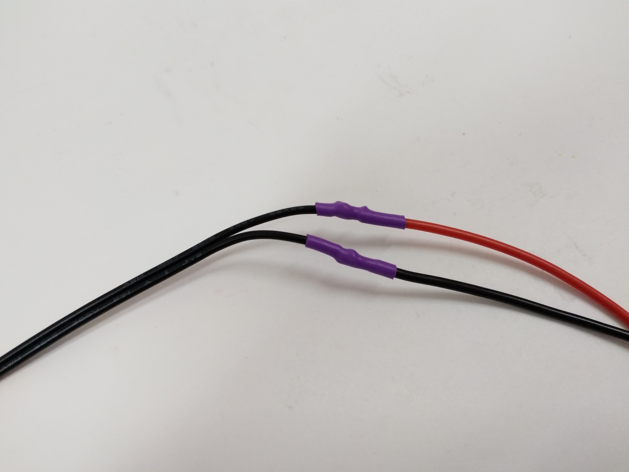
It covers the solder blobs nicely
-
-
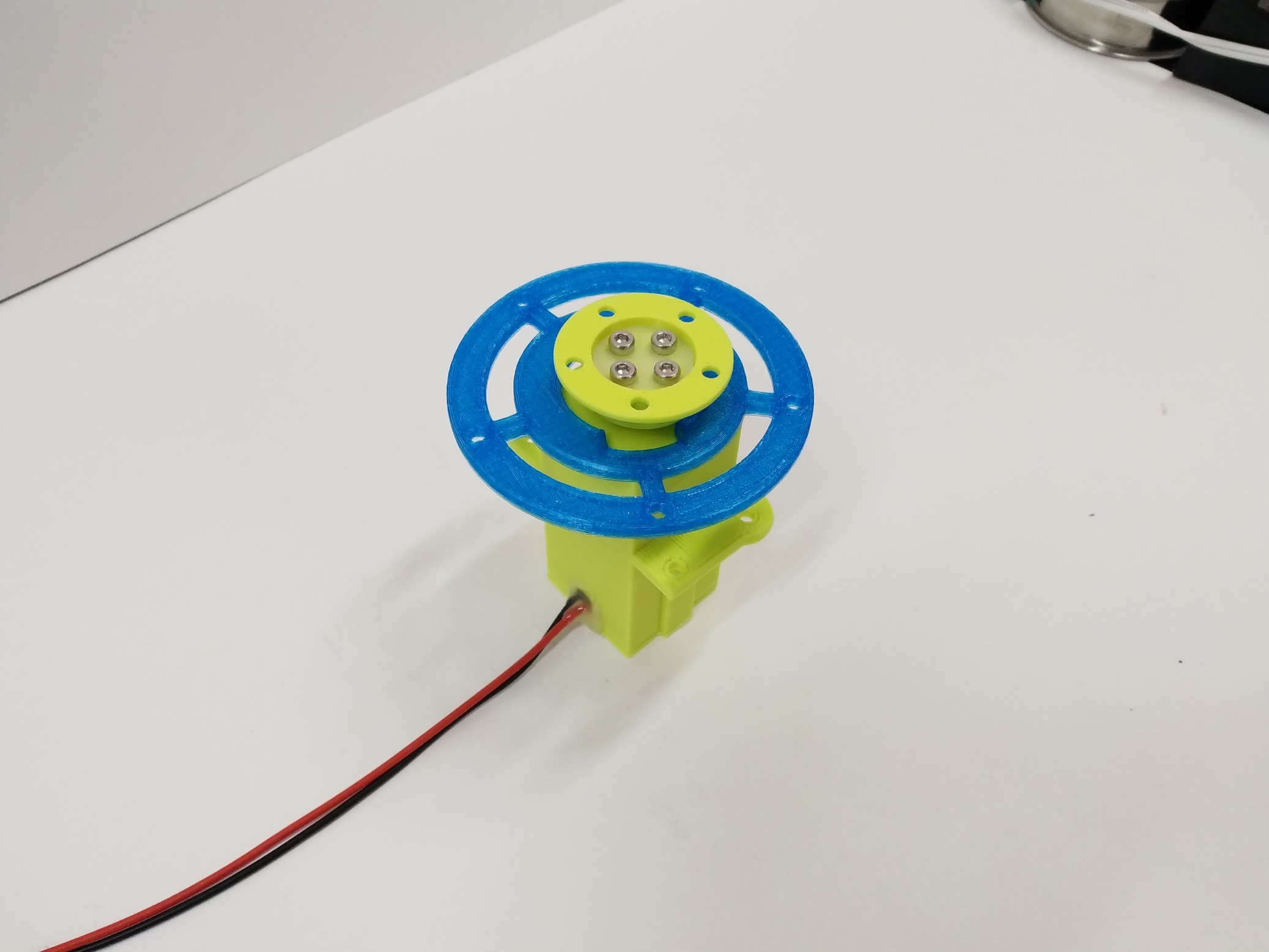
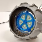
Colour scheme looks cool
-
-
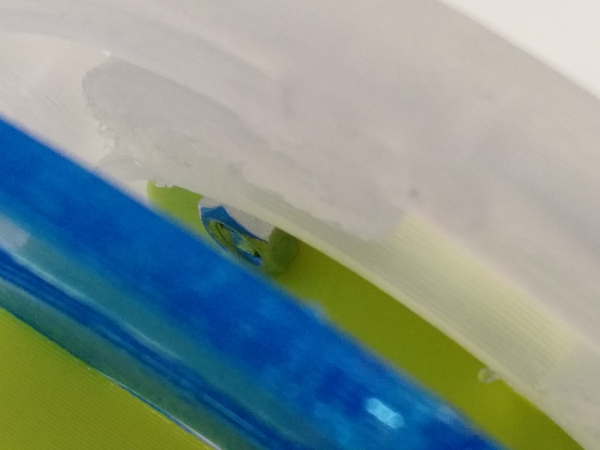
This is the cumbersome part – trying to attach that nut
-
-
There isn’t a lot of space to reach, and the screw doesn’t extend very far
-
-
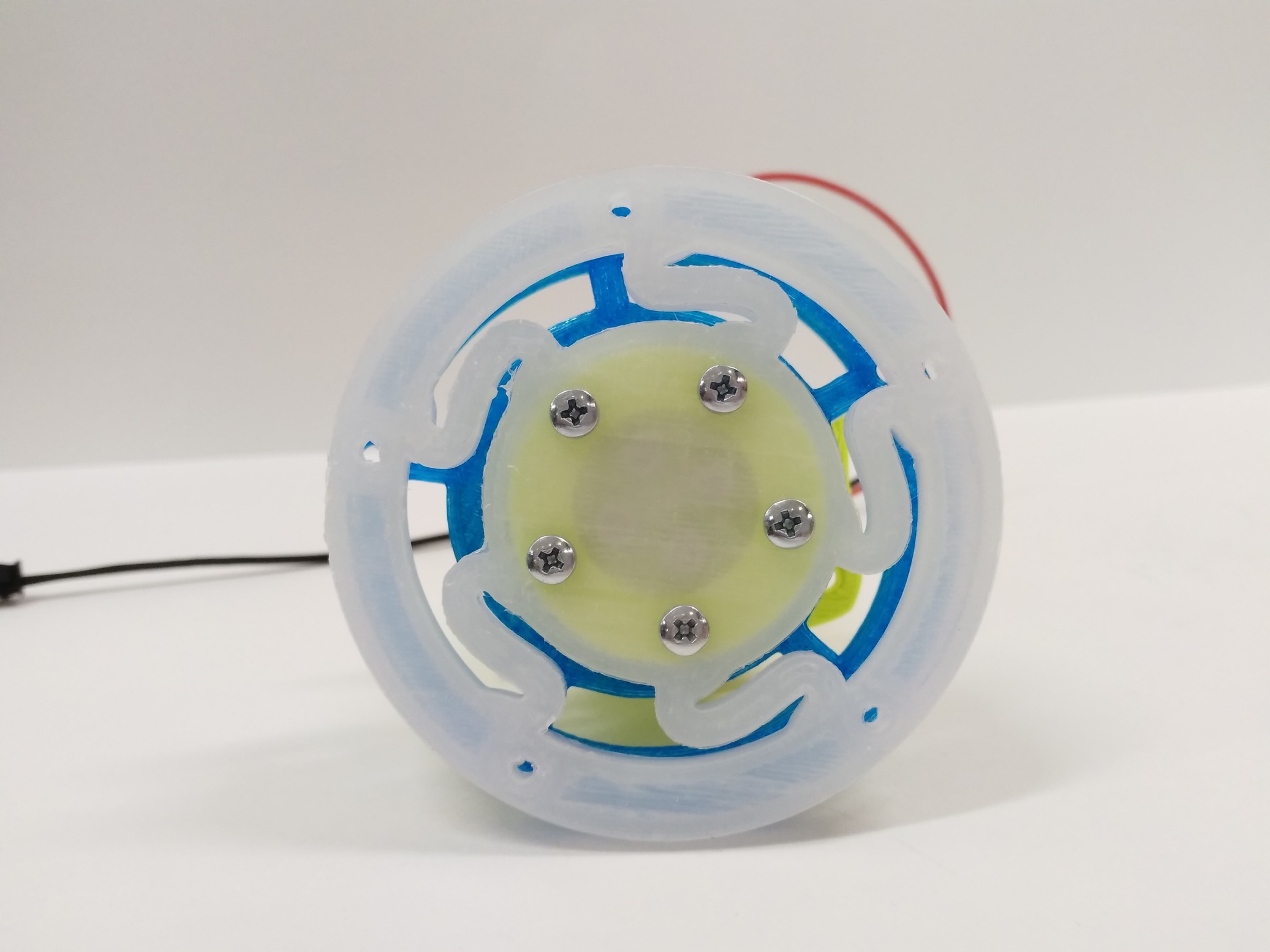
Eventually all 5 were added
-
-
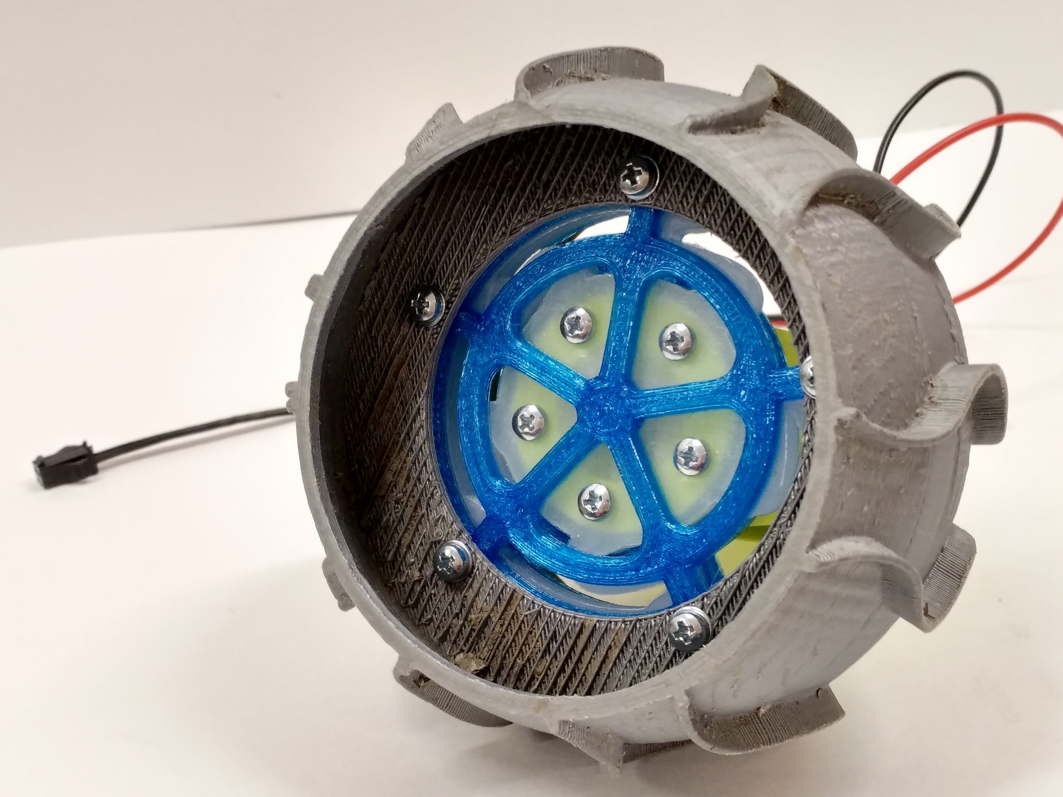
Then the front disk and the wheel added
-
-
If it looks familar, this was one of original bowie’s wheels that it used for several field tests
-
-
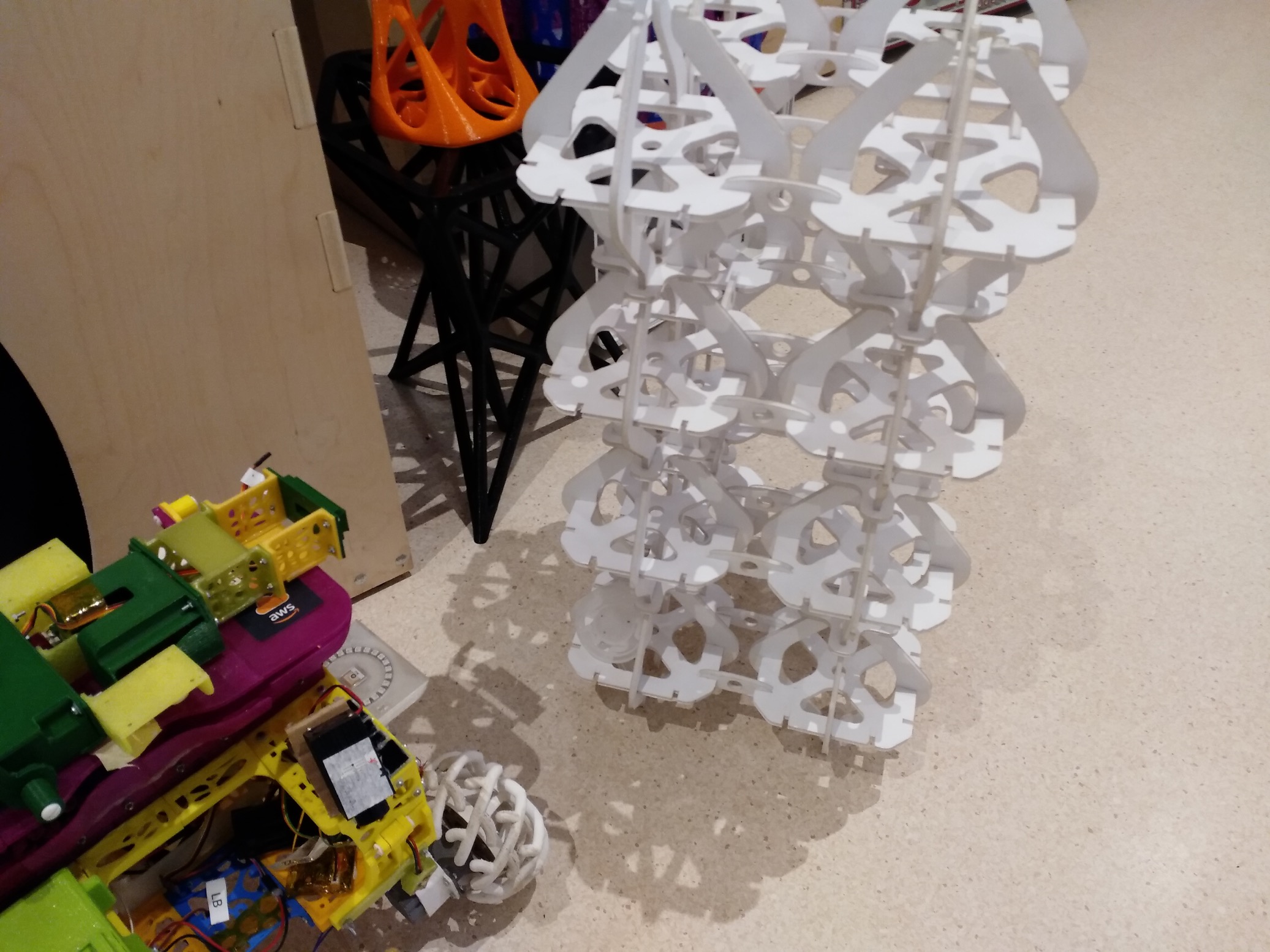
Kinda cool to see what has been assembled in the past weeks (not seen: brain kit)
There is a portion on the wheel kit that is very cumbersome to assemble. Not entirely sure the best way to go about organizing bug fixes / upgrades yet. Maybe one way would be to note down all the fixes that might be good to do after beta testing, then triage them into ones that will make the cut. Figuring out the priorities and figuring out support will be something to make sure is ready before the step by step guides go live. The last picture in the gallery is nice to see. Now these kits are on step 3 (brain kit: step 4).
Shoutout to Larry @fast_code_r_us for sending us a tip regarding an Arduino library for the OLED display. Check it out, the ss_oled library. Can’t wait to try this out once we circle back to the operator interface again. Saves us a bunch of time from researching and testing – so thanks for sending this along Larry!
by Erin RobotGrrl | Dec 17, 2019 | News, Progress Logs
There is progress being made on the operator interface assembly right now. Currently the display is completed. In the next few hours (after posting this brief log) will be the final steps on the keypad assembly. We received the components today which was a relief, in order to be able to document this tonight.
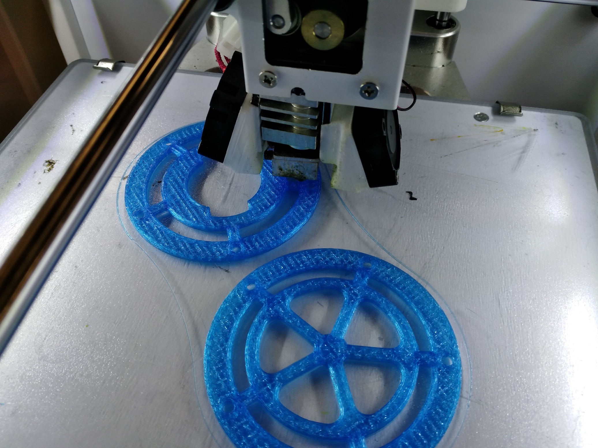
As for the motor kit, instead of the metal pieces we are increasing the disks from 2.5mm and 1.5mm to 3.0mm. This should add some more strength to it, while keeping it accessible via 3D printing – which is one of the main points of this Bowie robot in the first place. Looking at the CAD model, there should be enough clearance for a 16mm screw to have enough space at the end for the hex nut.
-
-
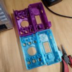
Adding the heatset inserts to the enclosure
-
-
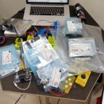
In the process of organising the parts for the kit
-
-
Checking alignment of heatsets with boards
-
-
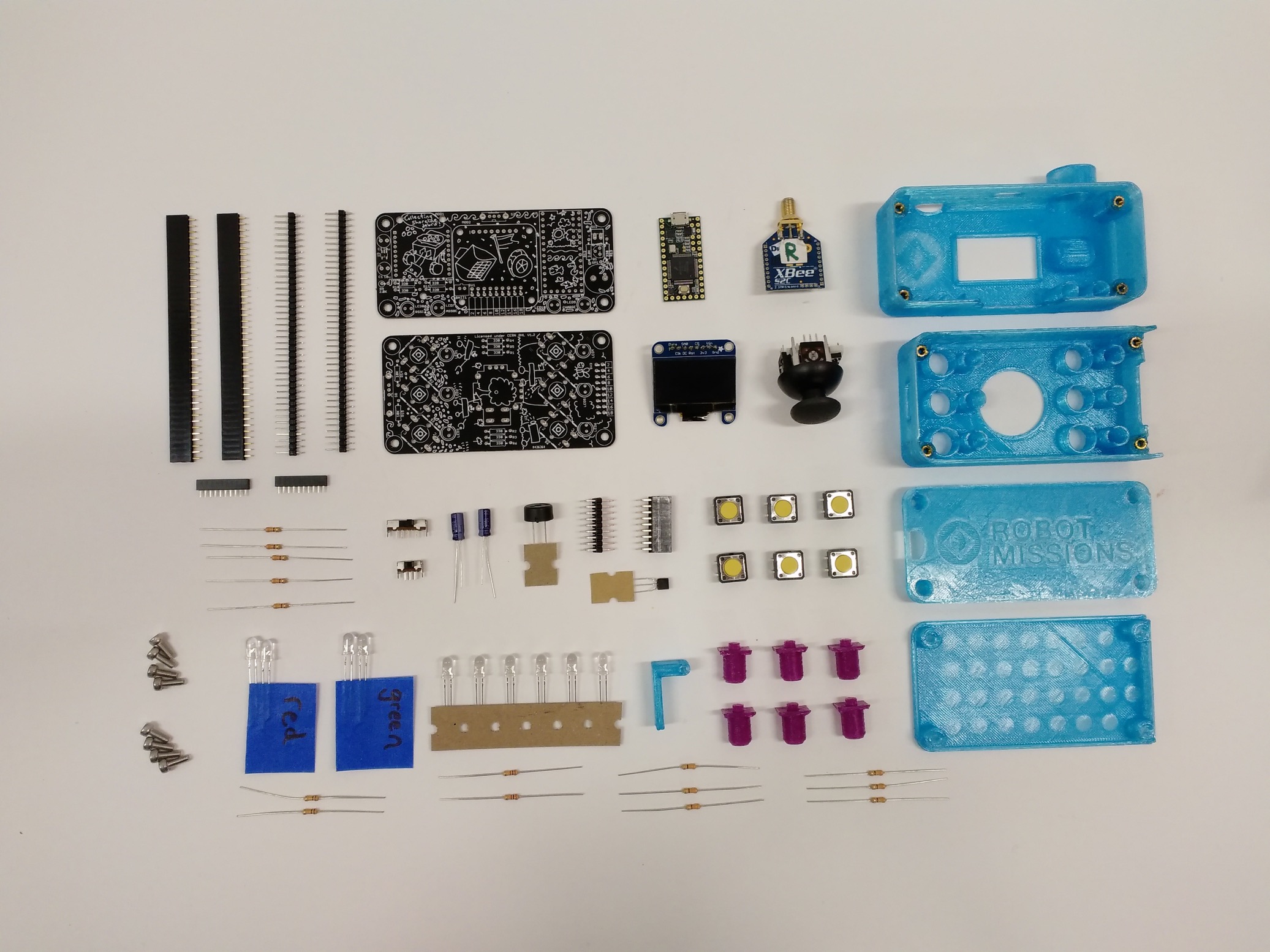
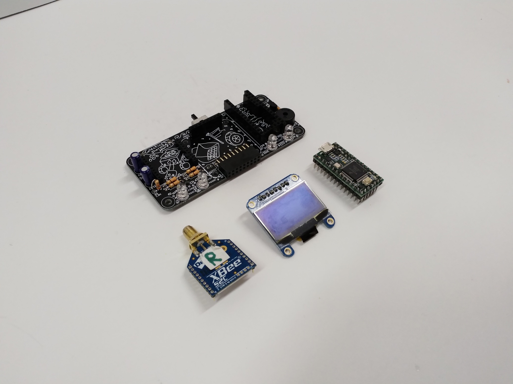
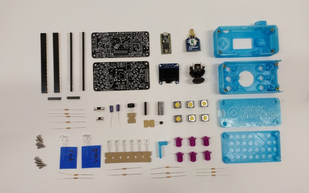
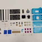
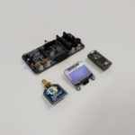
Components in the operator interface kit
-
-
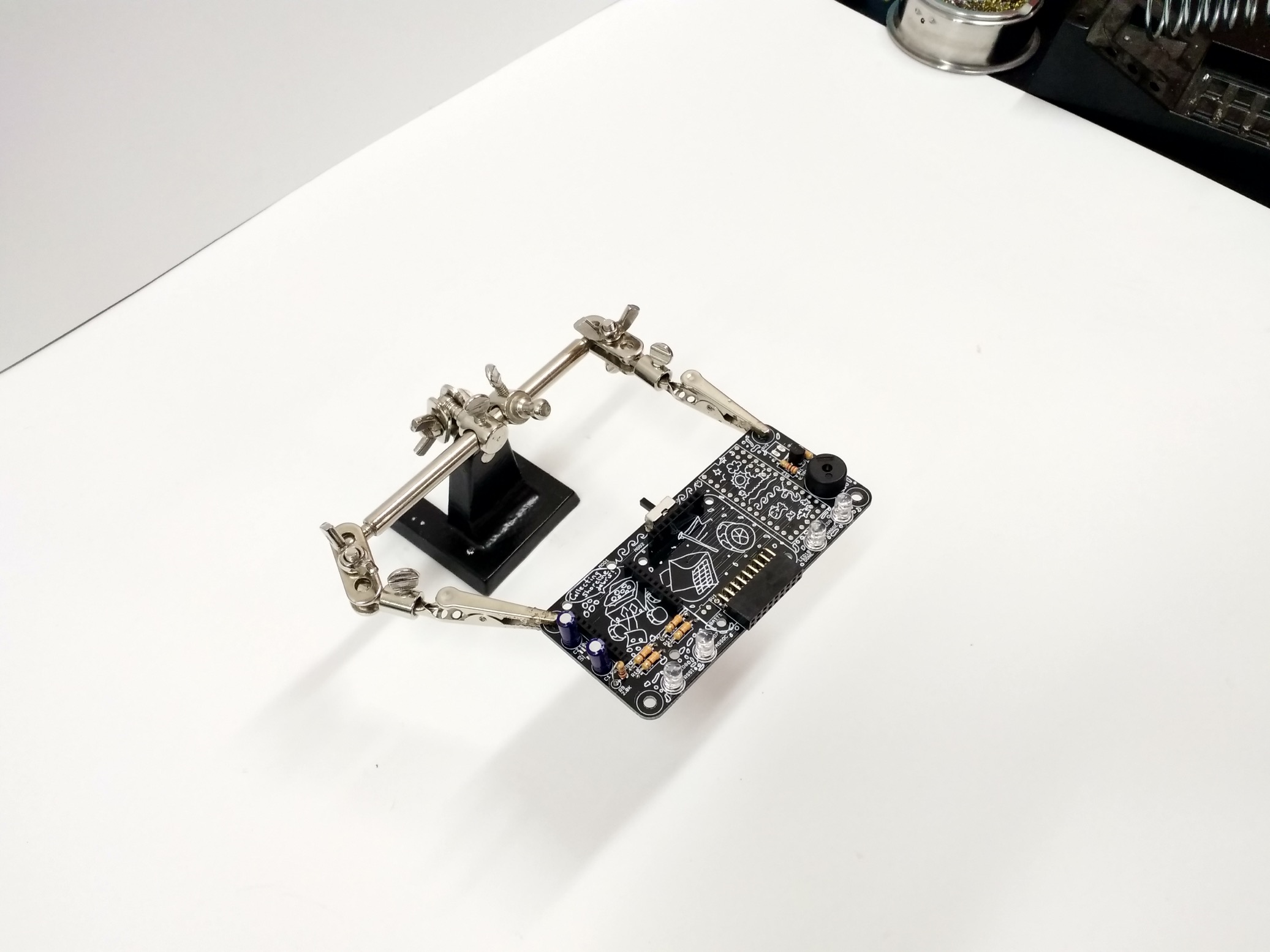
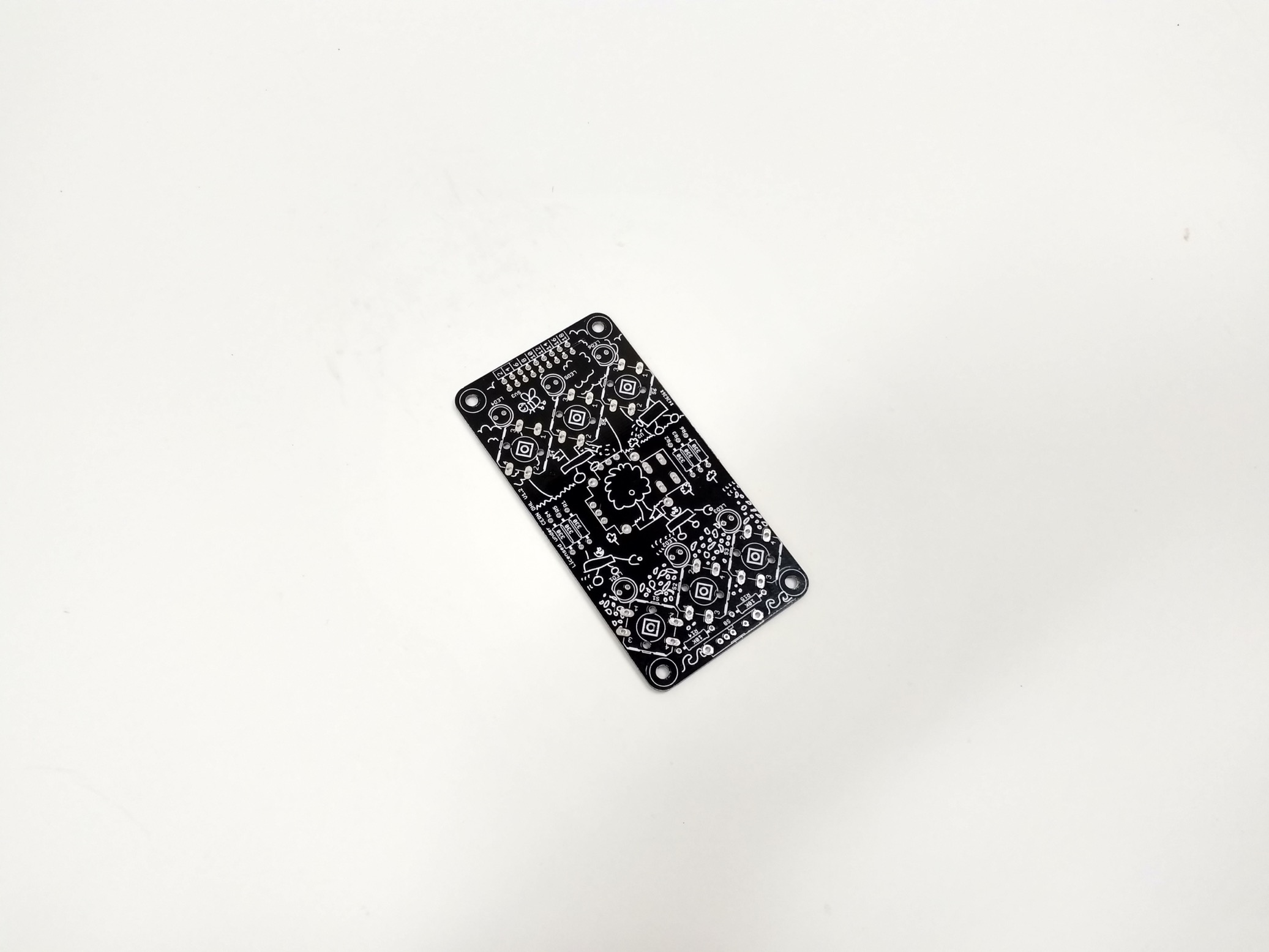
Starting the assembly process
-
-
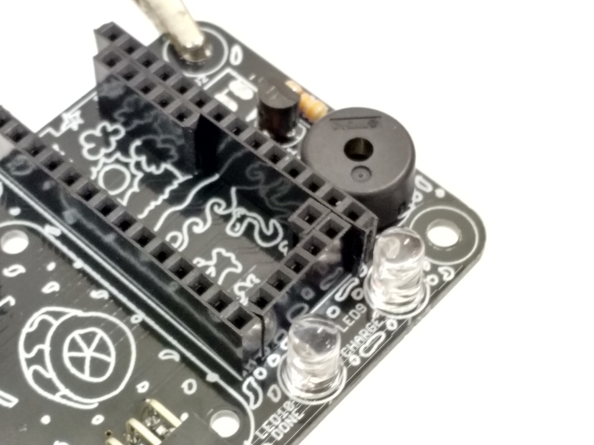
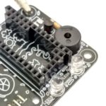
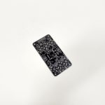
That is a 1 pin header in the corner
-
-
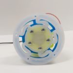
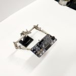
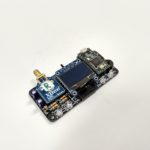
Now to add the xbee, display, and teensy
-
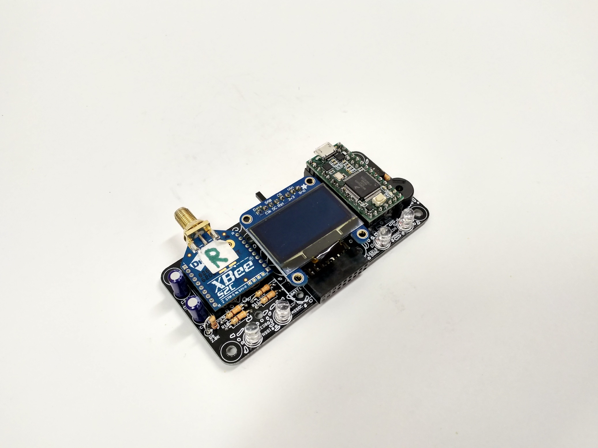
-
Assembled!
-
-
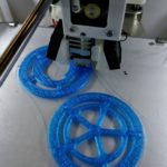
The thicker wheel plates are printing
-
-
Continuing work on the keypad next
What took up the most time so far tonight was the heatset inserts. The enclosures were previous versions without the proper hole dimension for the inserts. There’s also not enough clearance for the soldering iron tip tool to press the insert in without damaging the neighbouring walls. Finally, once the heatsets were in, then realised they weren’t aligned, so had to go back and attempt to manually align them with the circuit board. This will all be simpler with the updated version printed.
Now it is time to get back to assembling the operator interface keypad.