by Erin RobotGrrl | Dec 10, 2020 | News, Tech Logs
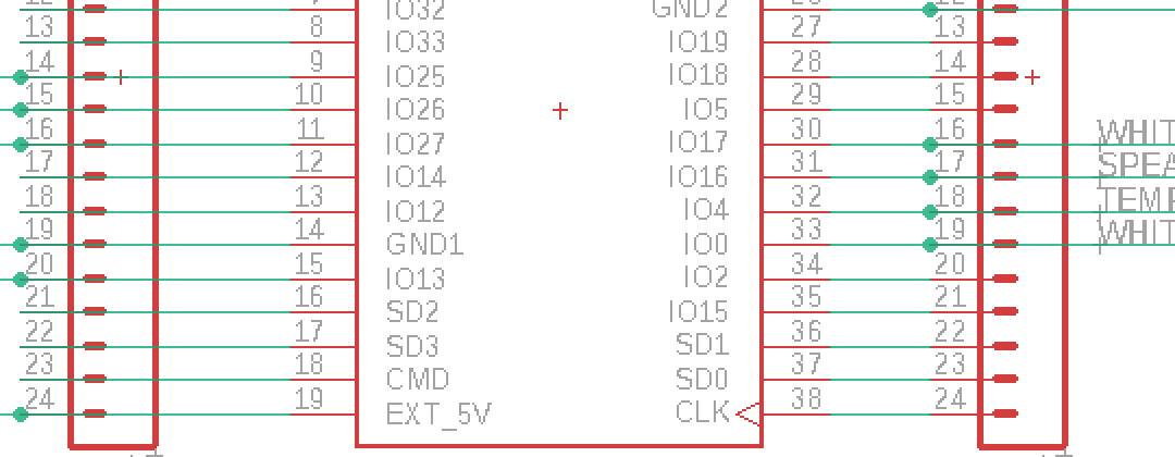
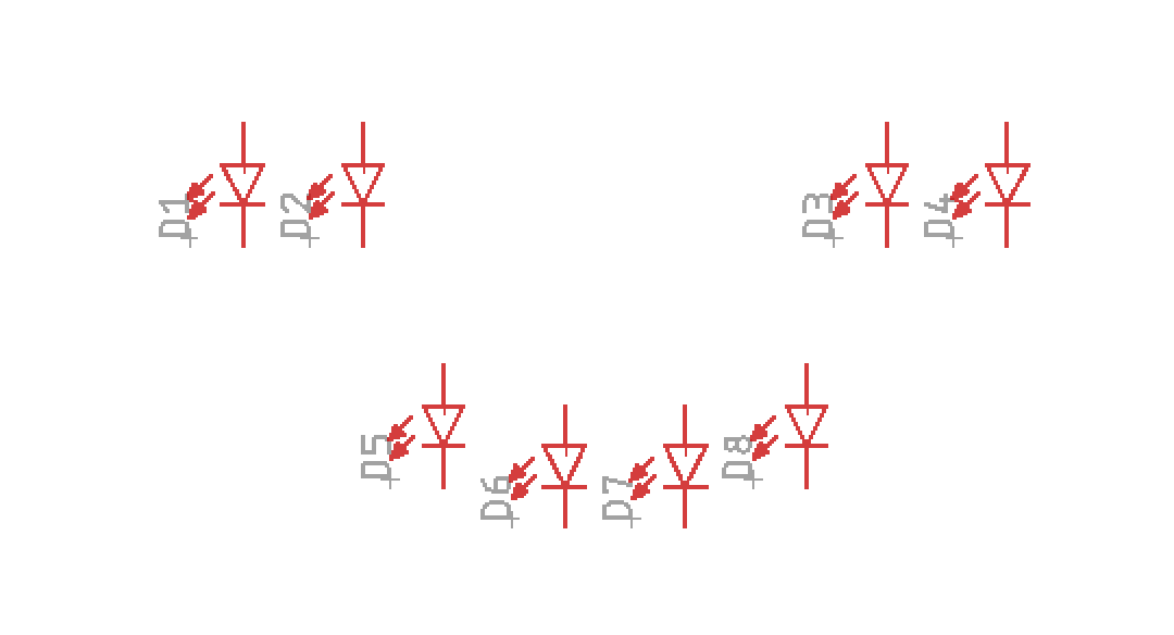
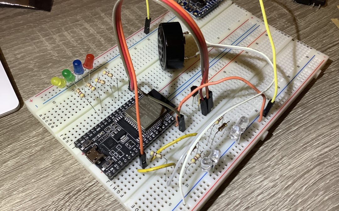
Schematic done for v0.1 of the sensor node! This is the most simplest design possible, with the barebones minimum. An ESP32 breakout, with headers to each side just in case, a reset switch, 6 LEDs, temperature sensor, speaker, and power boost board. All components are through hole at this moment in time. Pretty smooth sailing on this. Next step is to route the circuit board.
by Erin RobotGrrl | Dec 9, 2020 | News, Tech Logs
Basic code for the node to test input output functionality works. Two LEDs had to change pins as they were input only. PWM on ESP32 for LEDs is different than with the Arduino boards, that was interesting to learn about. Temperature sensor works, and analog input is 12 bit, so from 0 to 4095. Schematic is started. Next step is to complete the schematic, then board layout, and get the proper board outline with mounting holes into the design.
by Erin RobotGrrl | Dec 8, 2020 | News, Tech Logs
Determined the pins and wired them to the ESP32. Checked the recommended schematic for the temperature sensor, added a 0.1uF cap. There will be 4x white LEDs (2 individually controlled), and 1x red, blue, green, yellow. The purpose of each of these will be determined later when writing the code that connects with MQTT. The white LEDs illuminate an orange Nalgene quite nicely. Found a tone library for the speaker that works with the ESP32. Why use a breadboard for this and not jump right away to circuit board layout? Have run in to situations with the ESP32 where some pins behave differently than originally thought (for example, some pins are output only). Just verifying this works, then can make a pcb. Next step is to write the test code, then schematic capture and board layout. Yay, electronics!
by Erin RobotGrrl | Dec 7, 2020 | News, Tech Logs
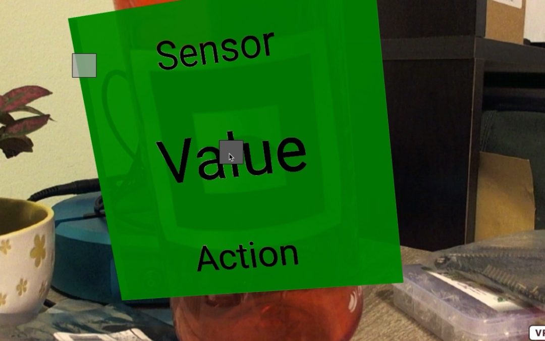
The drag & drop functionality now works! Check out the gif. By a count, about 8 methods were tried before reaching one that worked. Thought about the problem a bit differently, broke it down into tiny steps, and with a bit of tinkering, it works.
Dragging the square to the marker makes the marker change to green. Moving the marker to the square also makes it change to green.
The next step is to clean up the code that works, and integrate it with the ‘full’ codebase. After that, continue with the device hardware. There are plenty of ways to make it even better, but for now the aim is to make a complete working prototype.

by Erin RobotGrrl | Dec 4, 2020 | News, Tech Logs
There is a key piece of functionality for the user that is missing from the current AR mode of Terrapulse. That is, the user has to be able to drag and drop something onto the marker – and have an effect, like an animation or something. Eventually this would be used to display more information. Anyway, turns out that implementing this feature is not as straightforward. Spent most of the time searching for Aframe modules that would enable this. There’s one that kind of works, but needs some improvements. This will have to be looked at again tomorrow. Next step is to revisit this and try it again.