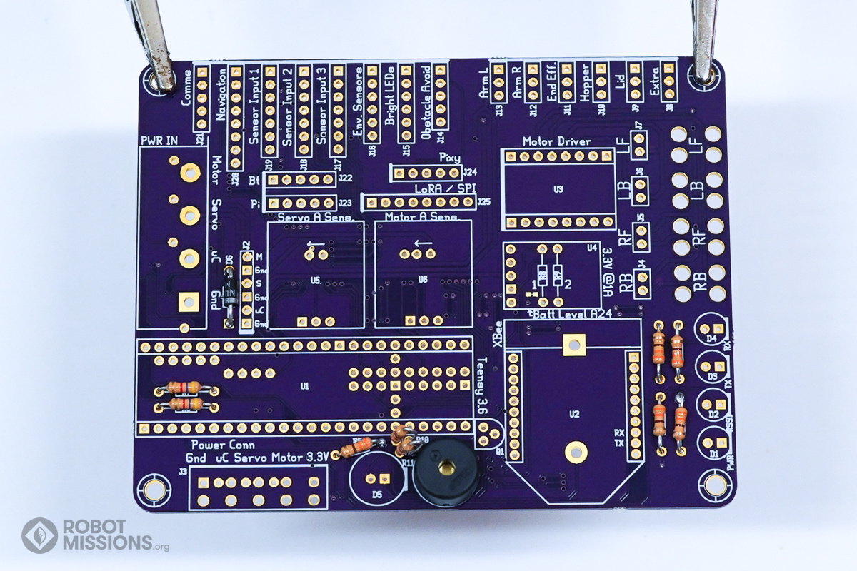
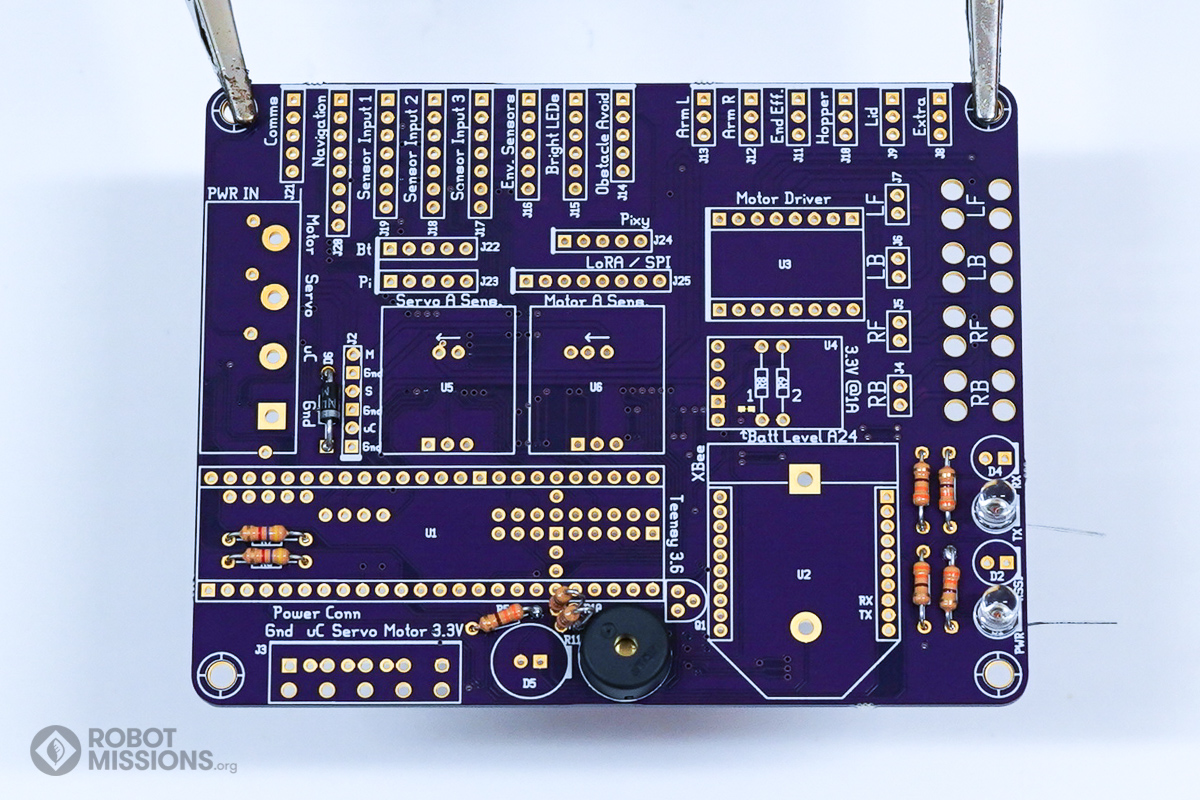
In this section, we will be adding the LEDs that illuminate when the XBee is in use, as well as the speaker that is used to indicate certain modes (or, just when Bowie is ‘singing’) ;). There is also the larger LED, which is used to indicate certain modes as well – for example, if you wanted to indicate that the robot is in autonomous mode. In this section you will need: 2x 5mm red and 2x 5mm green LEDs, a 10mm LED, and a speaker.
Insert the speaker in to LS.

This is the speaker inserted into LS.
Apply tape to the speaker to keep it in place. Then, flip the board over.
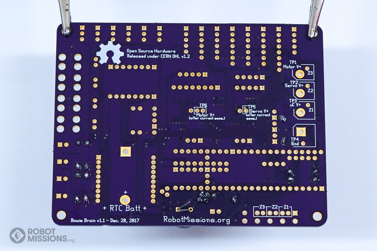
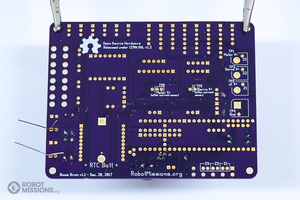
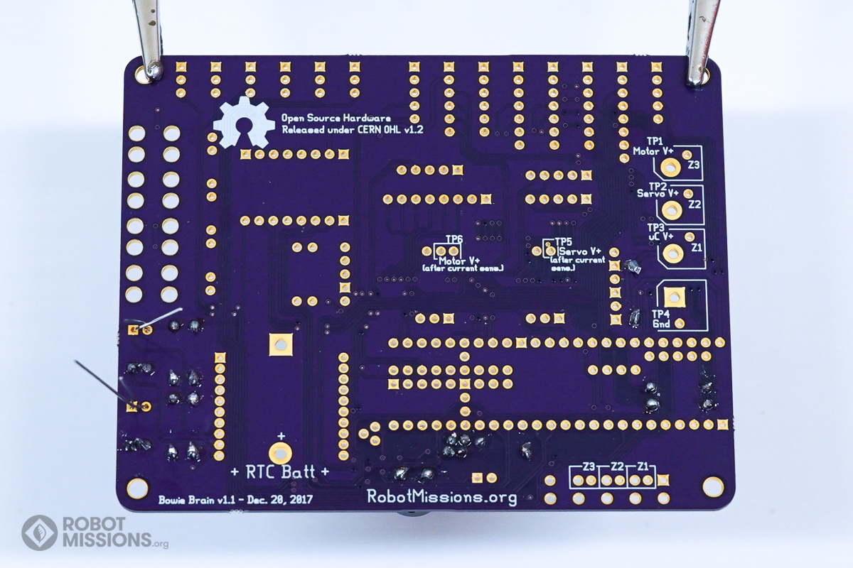
This is what the leads look like on the back of the board. Ensure that the component is still flush with the top side of the board, as it may have moved slightly during flipping.
This is what the leads look like on the back of the board. Ensure that the component is still flush with the top side of the board, as it may have moved slightly during flipping.
Solder the pads with your soldering iron and solder. Then, cut the leads using diagonal cutters. Once complete, flip the board over.
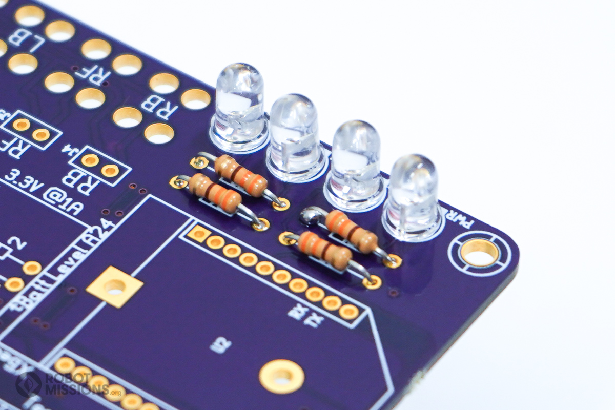
For the next couple of steps, please note the orientation of the LEDs for D1, D2, D3, and D4. The longer lead gets inserted into the solder pad with the circular ring around the hole. The shorter lead gets inserted into the solder pad with the square around the hole. Additionally, the ‘flat’ of the LED will be towards the right edge of the board, where the white line is on the silkscreen.
Insert the two 5mm red LEDs into D1 and D3.
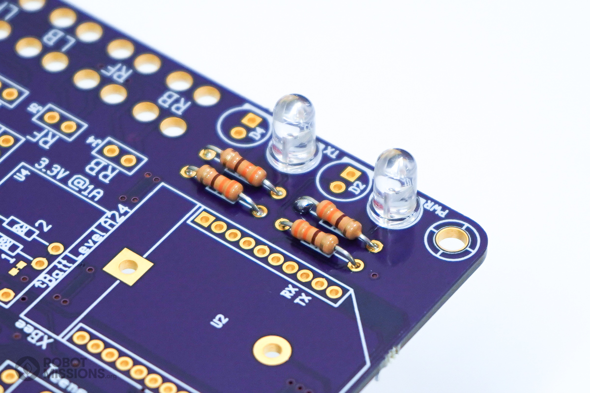
Here are the two red LEDs inserted into D1 and D3.
Twist the leads of the LED together. Then, flip the board over.
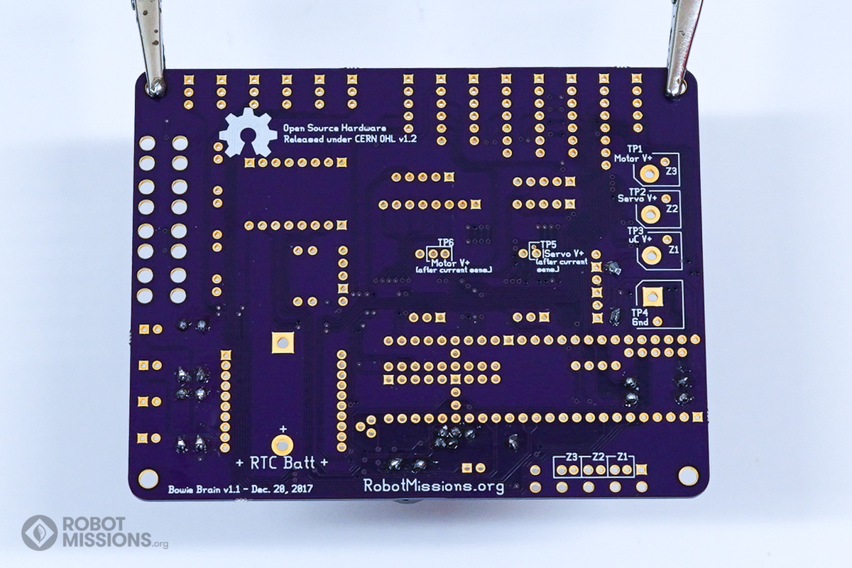
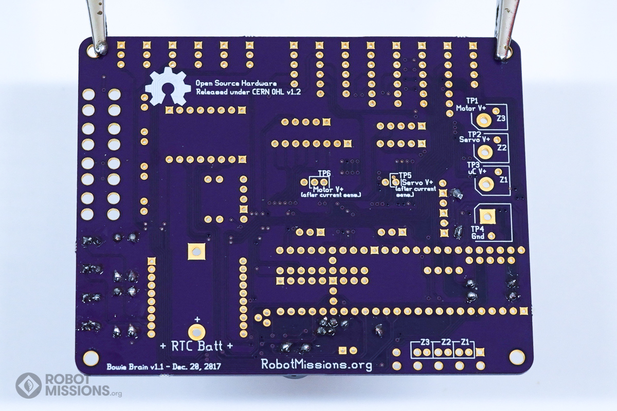
This is what the leads look like on the back of the board. Ensure that the components are still flush with the top side of the board, as it may have moved slightly during flipping.
This is what the leads look like on the back of the board. Ensure that the components are still flush with the top side of the board, as it may have moved slightly during flipping.
Solder the pads with your soldering iron and solder. Then, cut the leads using diagonal cutters. Once complete, flip the board over.
Insert the two 5mm green LEDs into D2 and D4.
Here are the green LEDs inserted.
Twist the leads of the LEDs together. Then, flip the board over.
This is what the leads look like on the back of the board. Ensure that the components are still flush with the top side of the board, as it may have moved slightly during flipping.
This is what the leads look like on the back of the board. Ensure that the components are still flush with the top side of the board, as it may have moved slightly during flipping.
Solder the pads with your soldering iron and solder. Then, cut the leads using diagonal cutters. Once complete, flip the board over.
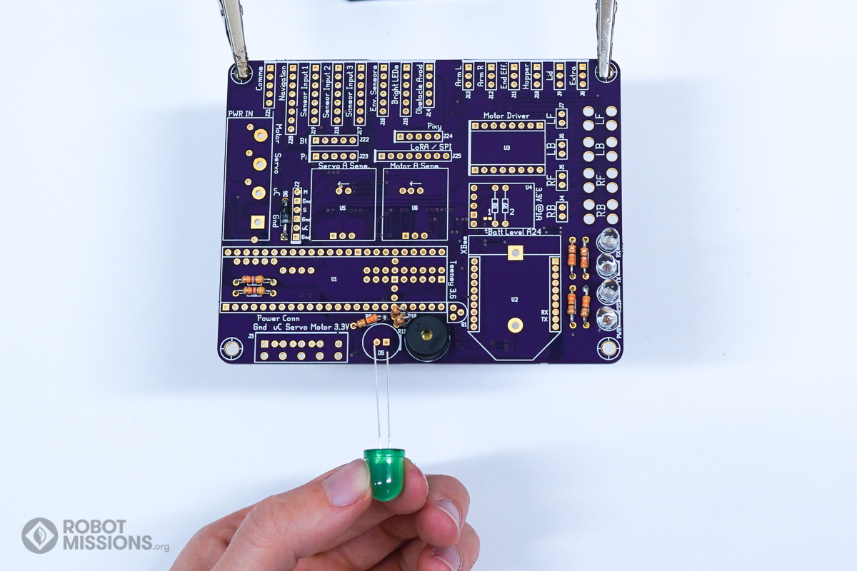
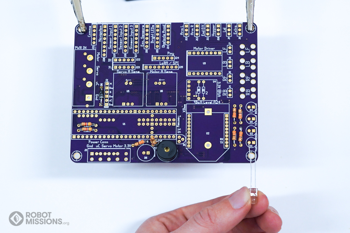
Note the orientation for the large 10mm LED to be inserted in D5. The longer lead gets inserted into the solder pad with the circular ring around the hole. The shorter lead gets inserted into the solder pad with the square around the hole. Additionally, the ‘flat’ of the LED is facing the right, as indicated by the white line on the silkscreen.
Insert the 10mm LED into D5.
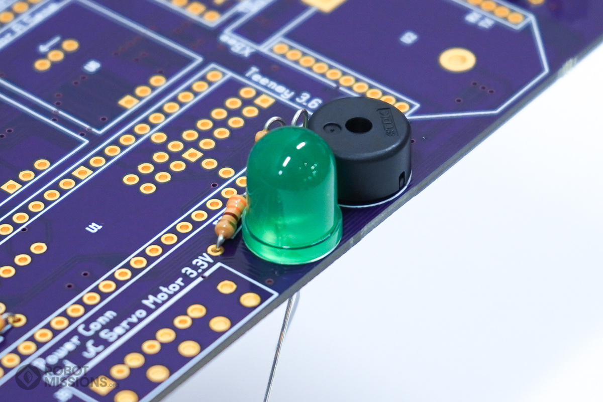
Here is the LED inserted into D5.
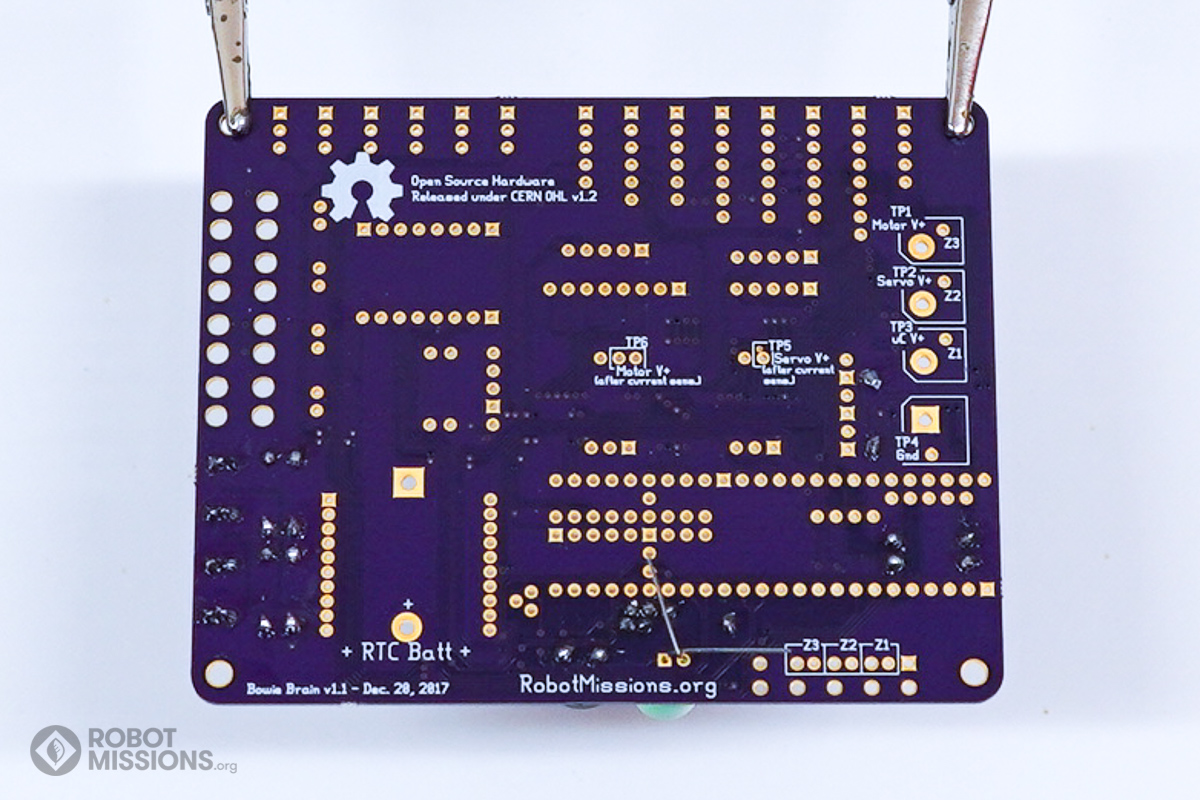
Twist the leads of the LEDs together. Then, flip the board over.
This is what the leads look like on the back of the board. Ensure that the components are still flush with the top side of the board, as it may have moved slightly during flipping.
This is what the leads look like on the back of the board. Ensure that the components are still flush with the top side of the board, as it may have moved slightly during flipping.
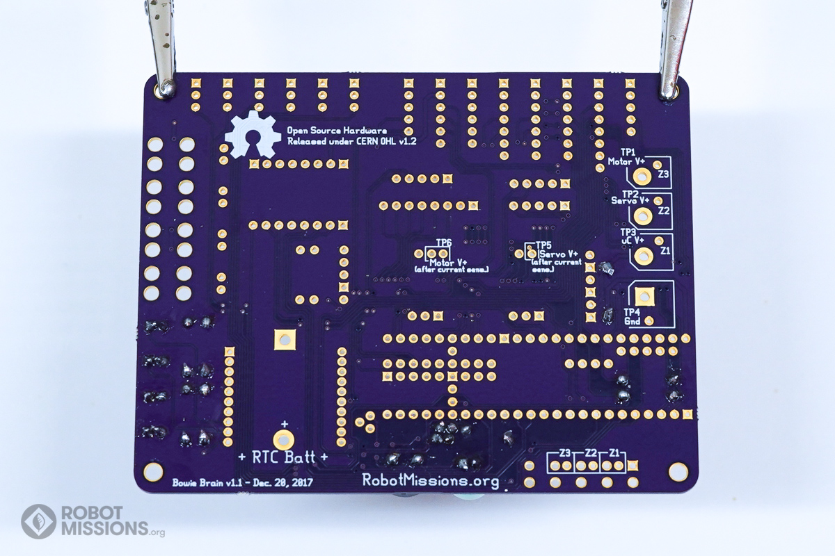
Solder the pads with your soldering iron and solder. Then, cut the leads using diagonal cutters. Once complete, flip the board over.
| ← First components: resistors and diodes | Regulator, transistor, and inputs → |