In this part we will be wiring the DC motor to the connector that interfaces with the Bowie Brain. For this part you will need the motor, wires, heat shrink, and the JST-SM connector.
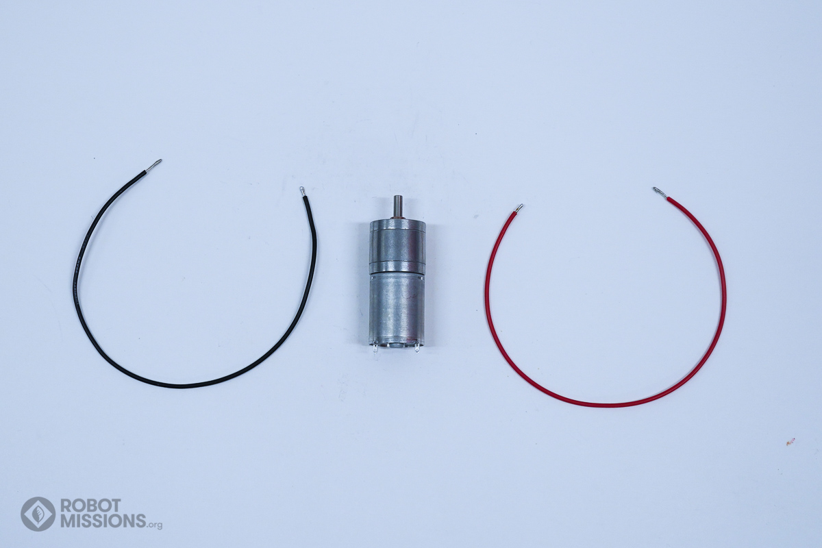
Start by obtaining the DC motor, and one 18cm positive wire, and one 18cm negative wire. Strip the ends of the wires and tin them with solder.
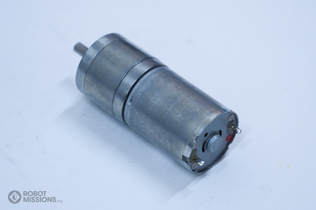
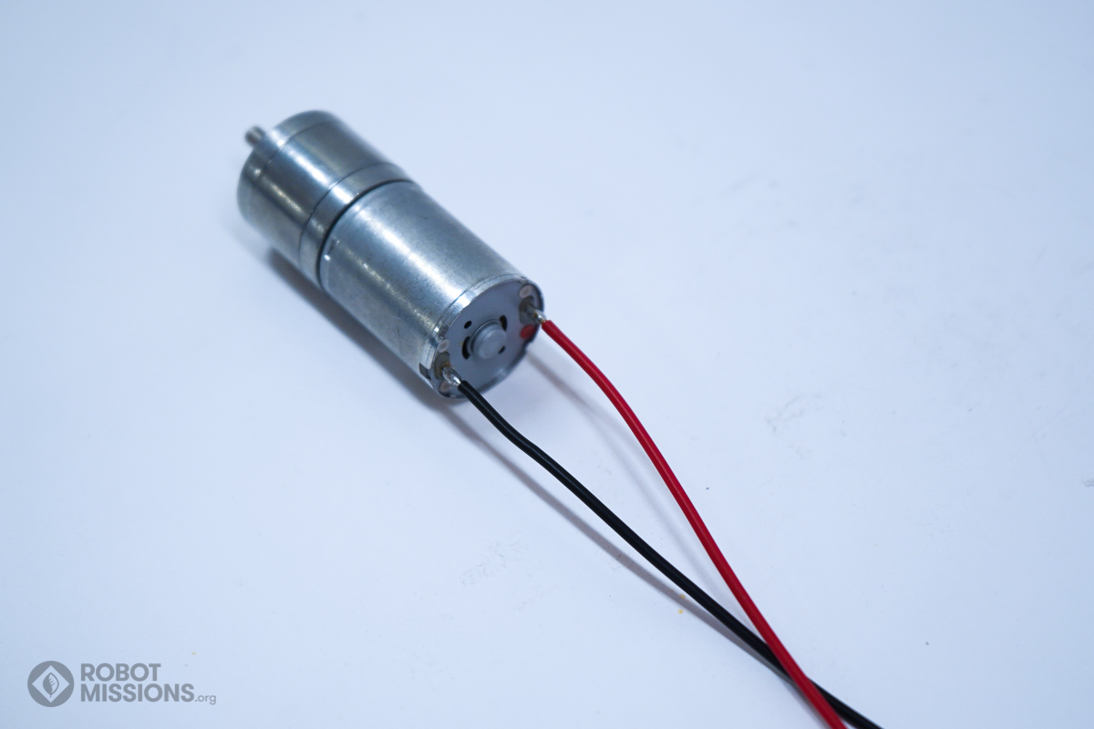
Here is the DC motor. Notice the red dot near the right-most terminal.
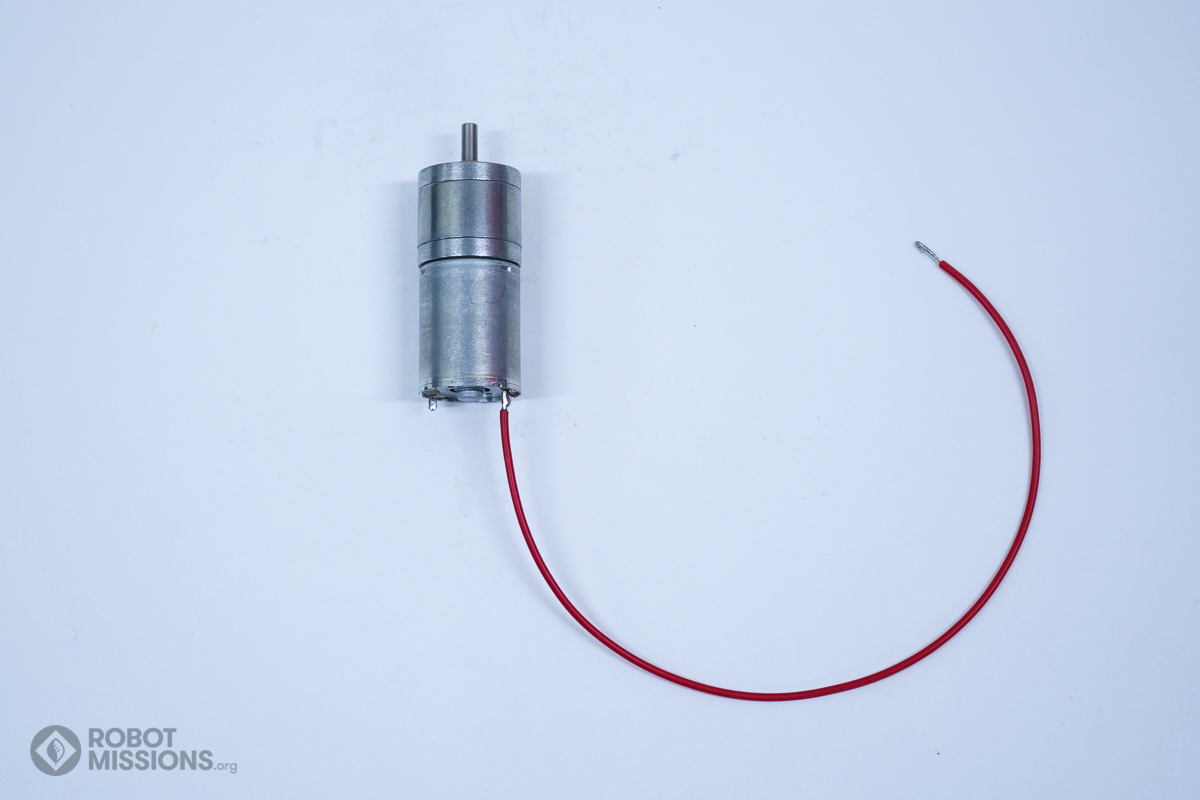
Solder the positive wire to the terminal with the red dot closest to it.
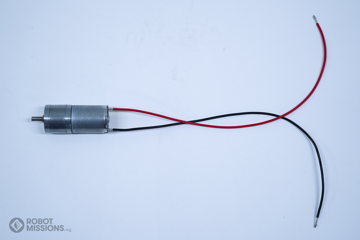
Solder the negative wire to the other terminal.
Ensure the solder connections are secure.
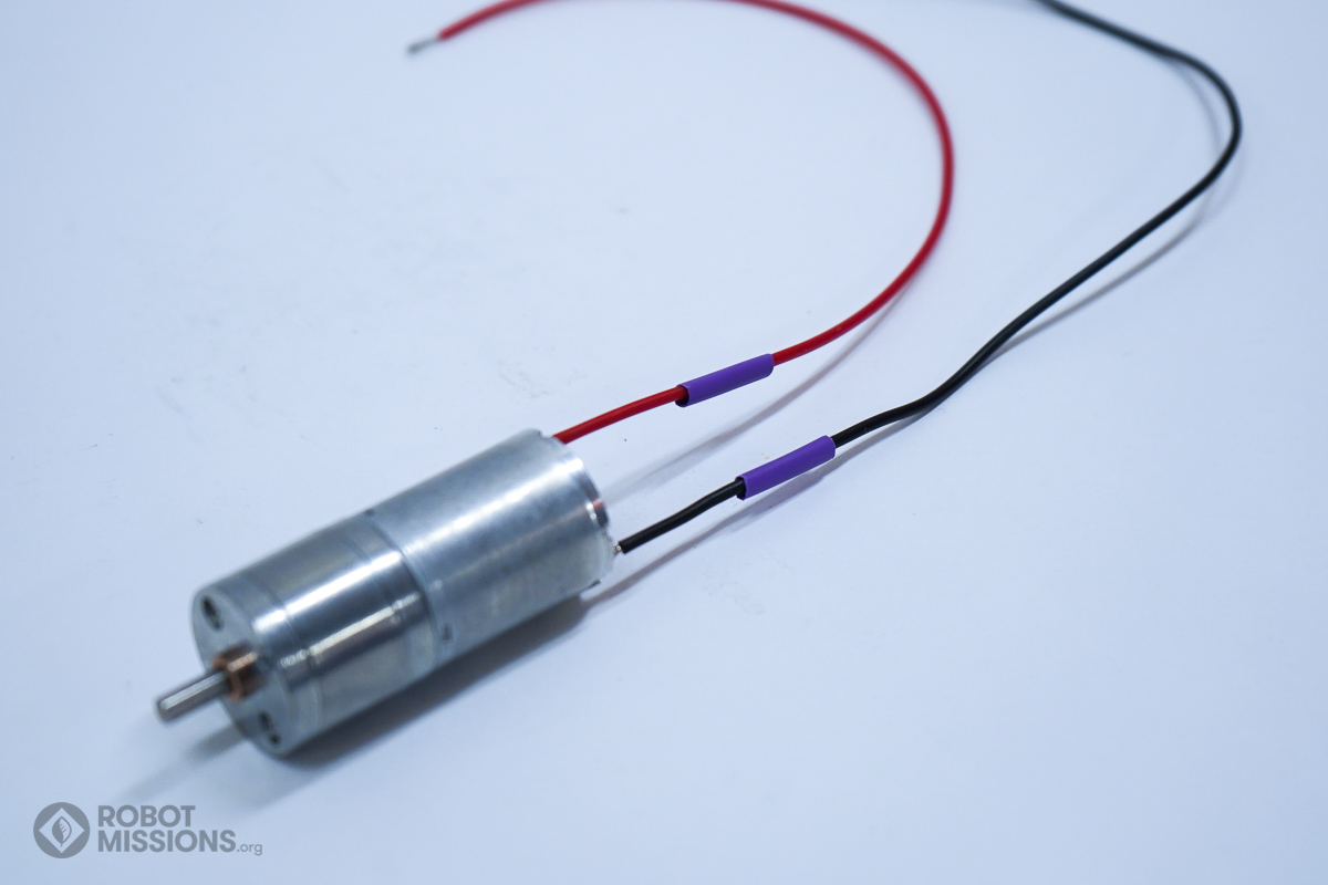
Run a 25.4mm tube of heat shrink onto both wires. Do not heat to shrink them just yet.
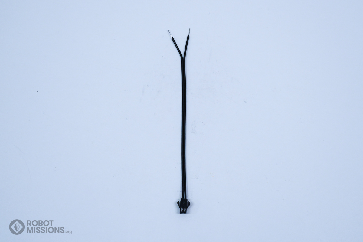
Obtain the JST-SM connector. In this orientation of the wire (pointing down, with the shiny terminals up) the wire on the left is negative, and the wire on the right is positive. Label these wires using tape and a sharpie marker. The wire ordering is important, because it will make it easier down the line when swapping out drive systems on your robot on the fly.

Strip the ends of the wires to be approximately 10mm. Do not tin the tips yet.
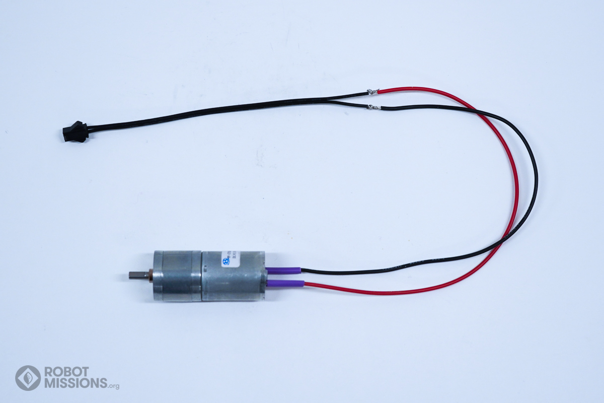
Connect the JST-SM wires to the positive and negative wires from the motor. Correspond the labeled wires on the JST-SM wires to go from negative to negative, and positive to positive.
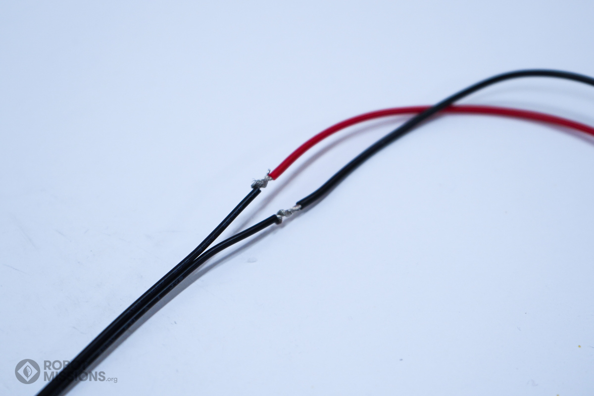
Here is a closer look at how the wires can connect together. Twirling the wires around each other.
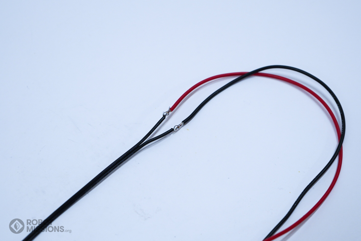
Solder the connected wires together.
Slide the heat shrink tubing over the soldered areas.
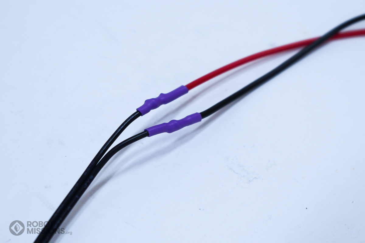
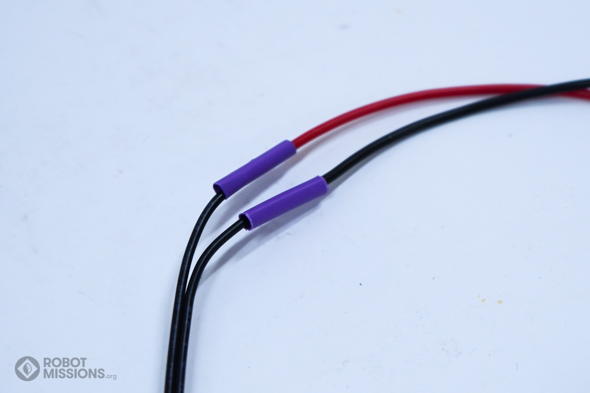
Apply heat to the heat shrink tubing to completely shrink it around the soldered areas. You can do this by hovering your soldering iron underneath it, with an air gap of 3mm. Rotate the wire to apply the heat evenly.
| ← Introduction | Enclosing motor part A → |