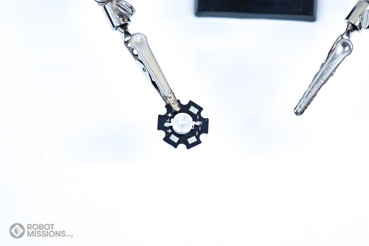
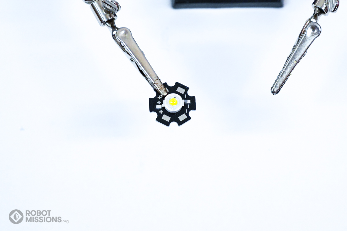
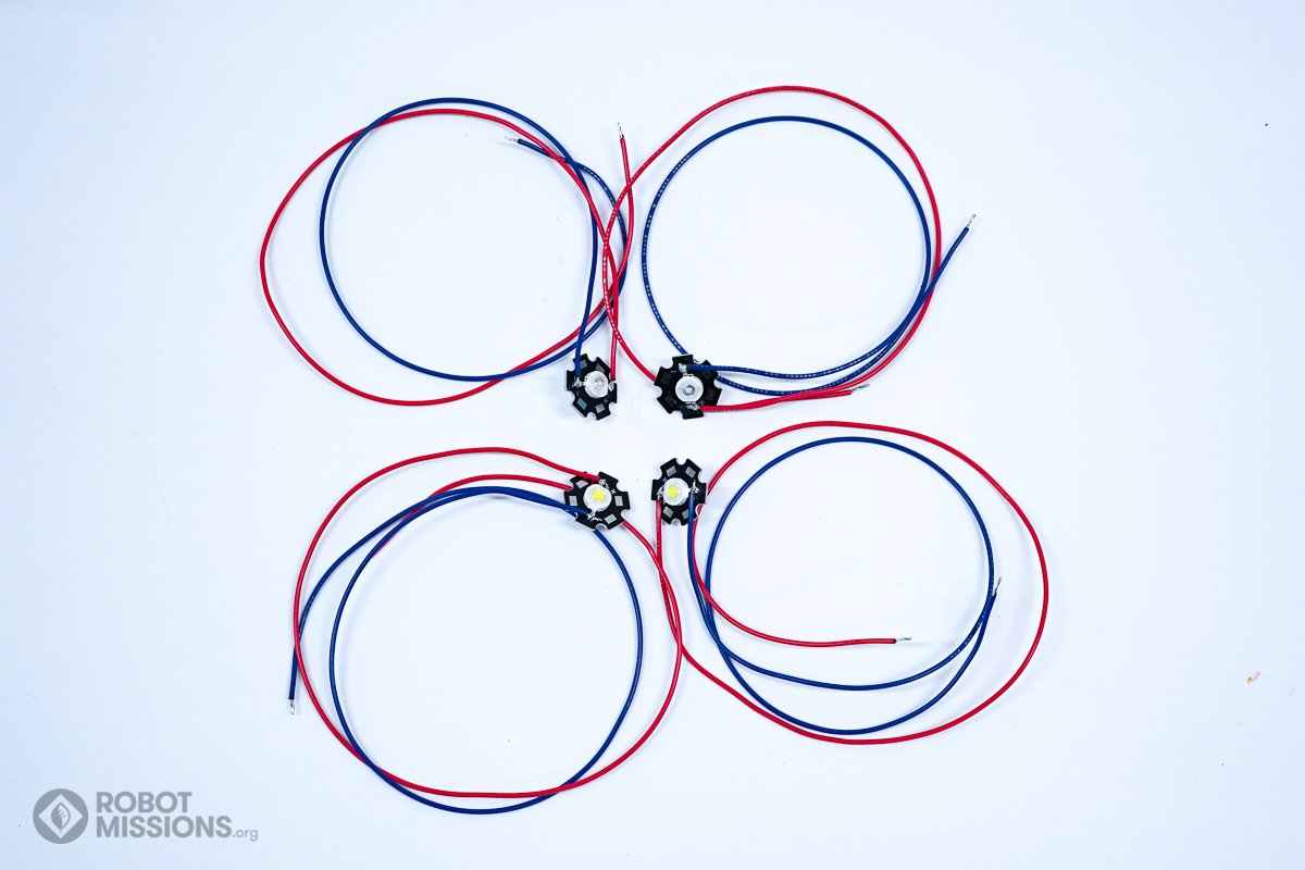
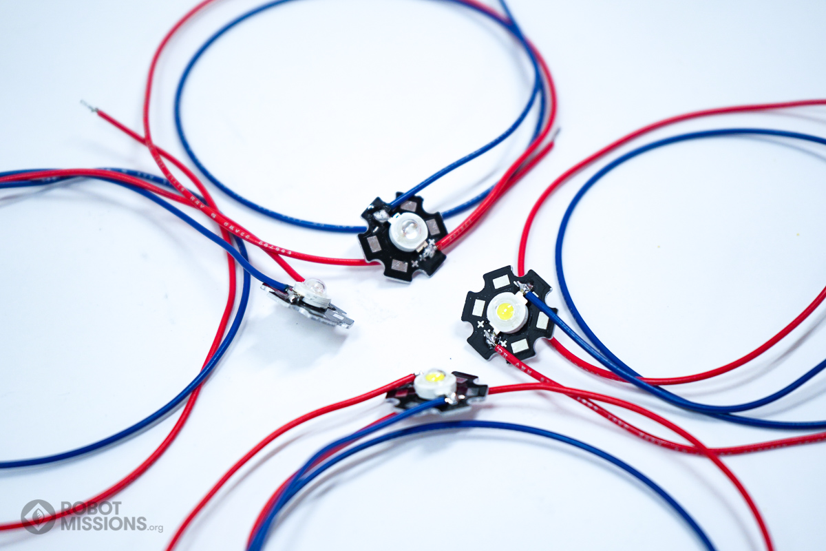
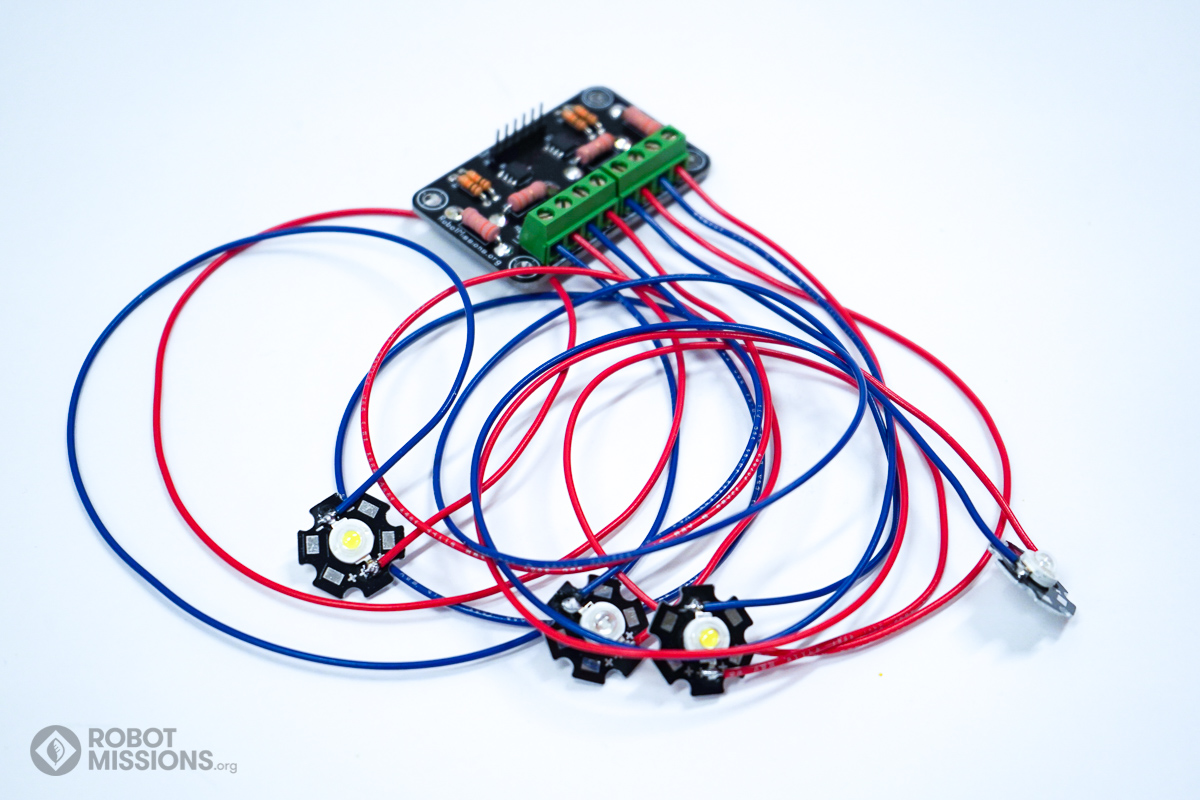
In this part we will solder the wires to the LEDs. The blue LEDs are the ones with a more ‘clear’ lens, and the white ones have a tinge of yellow phosphor. For this part you will need all 4 of the LEDs and all 8 of the wires.
Obtain the super bright LEDs. The first one to select is the blue one. The blue ones are ‘clear’ coloured, as they do not have the yellow tinted phosphor. Step 1-4 is to be repeated twice for each blue LED.
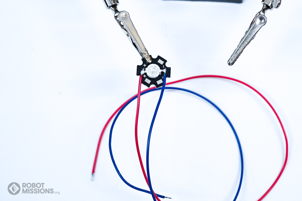
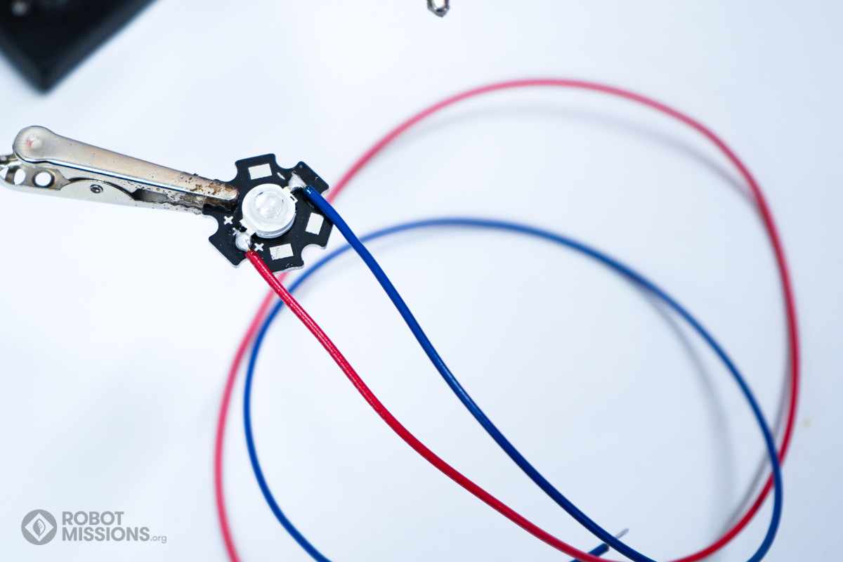
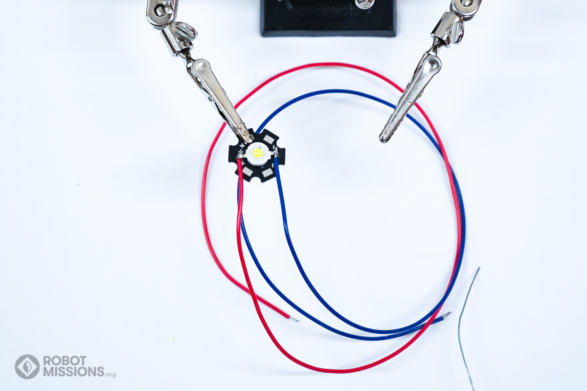
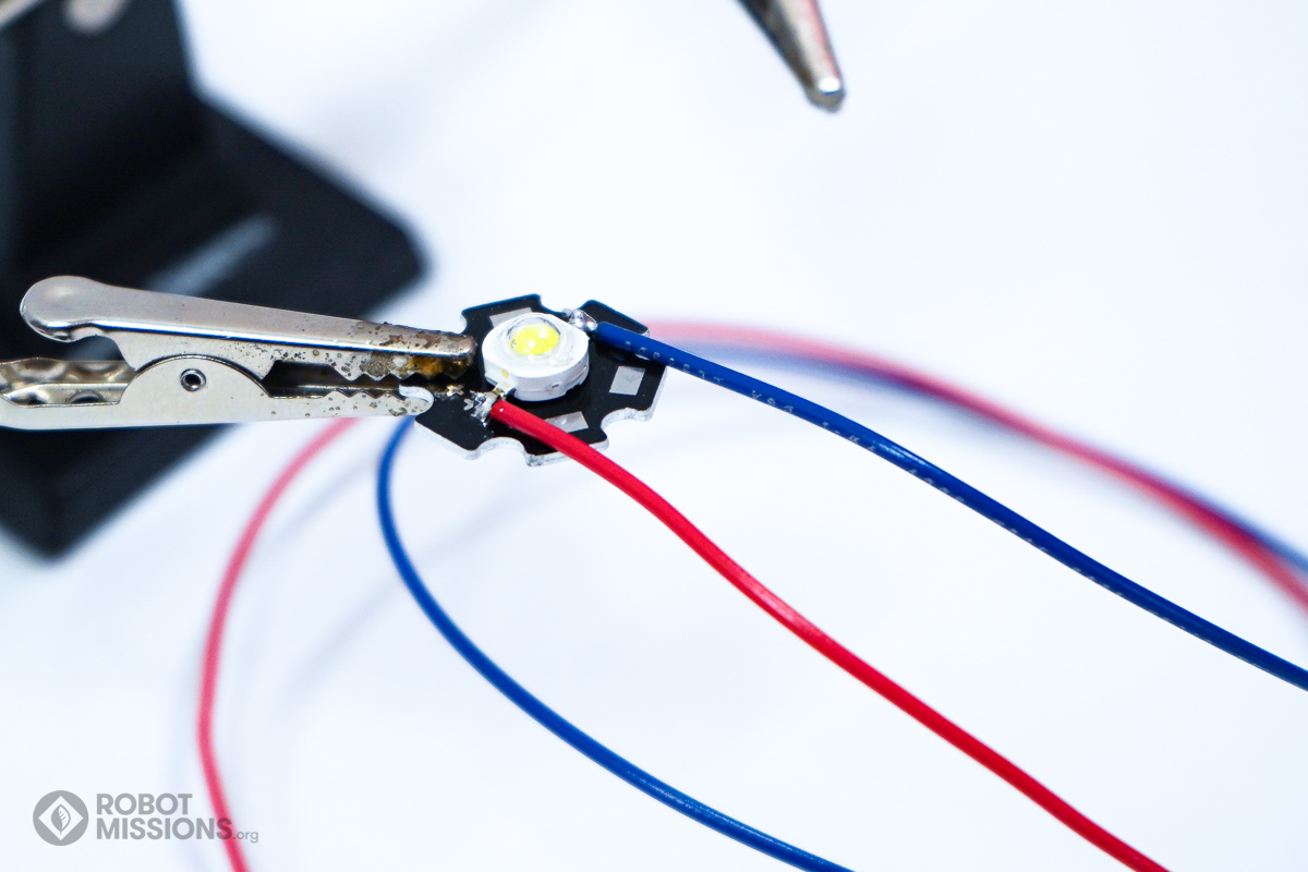
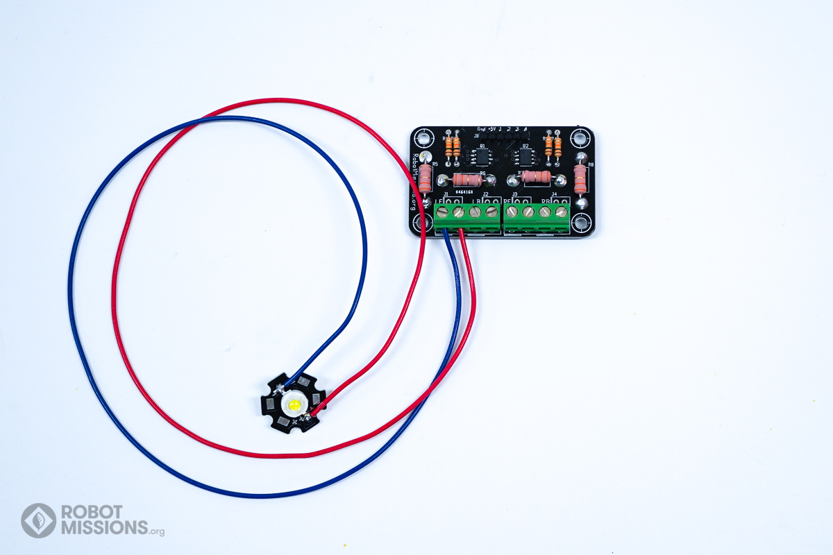
Solder the positive wire onto the terminal of the LED that has the + labeled next to it. Solder the negative wire onto the terminal of the LED that has the – labeled next to it.
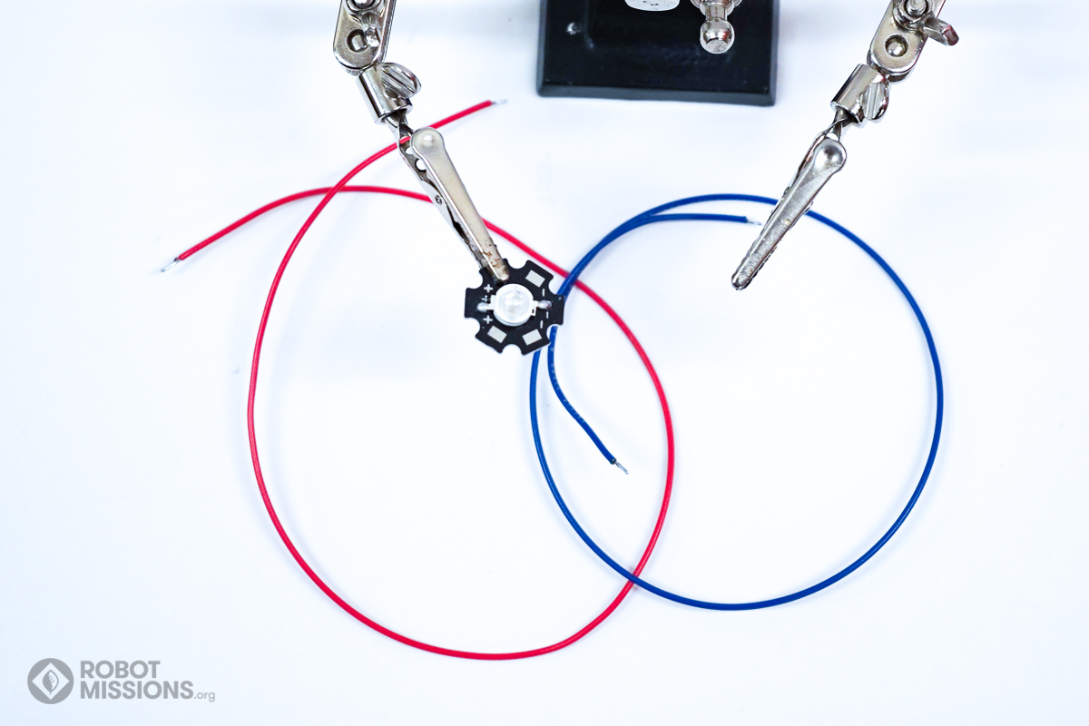
With the wires that were cut in the initial part, obtain the 42cm positive and 42cm negative wire. Strip the ends of the wire and tin the tips.
Solder the positive wire onto the terminal of the LED that has the + labeled next to it. Solder the negative wire onto the terminal of the LED that has the – labeled next to it.
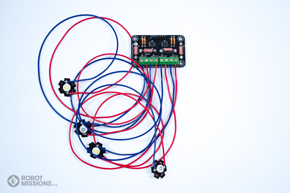
Insert the first white LED into the screw terminal labeled ‘LF’. The negative wire goes in to the terminal with the thicker white line on the circuit board.
Using a screwdriver and proper bit, loosen the screw terminals prior to inserting the wires. Then, tighten the screw terminals.
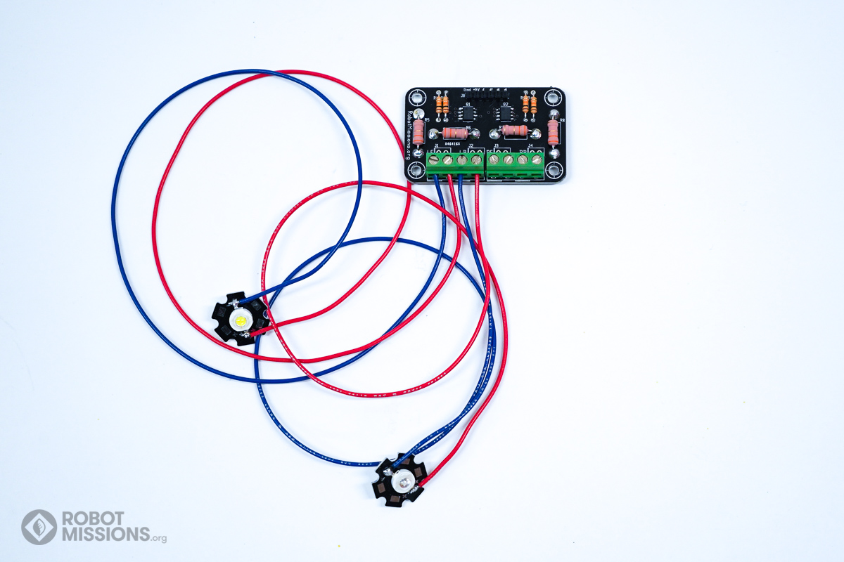
Insert the first blue LED into the screw terminal labeled ‘LB’. The negative wire goes in to the terminal with the thicker white line on the circuit board.
Using a screwdriver and proper bit, loosen the screw terminals prior to inserting the wires. Then, tighten the screw terminals.
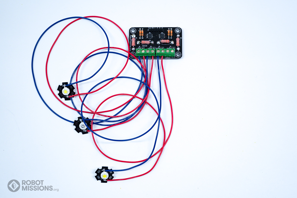
Insert the second white LED into the screw terminal labeled ‘RF’. The negative wire goes in to the terminal with the thicker white line on the circuit board.
Using a screwdriver and proper bit, loosen the screw terminals prior to inserting the wires. Then, tighten the screw terminals.
This LED will be for the front right of the robot.
Insert the second blue LED into the screw terminal labeled ‘RB’. The negative wire goes in to the terminal with the thicker white line on the circuit board.
Using a screwdriver and proper bit, loosen the screw terminals prior to inserting the wires. Then, tighten the screw terminals.