In this part, we will add some more headers. See the steps below for which headers, how many pins, and where, are necessary.
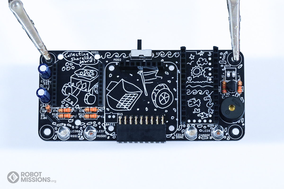
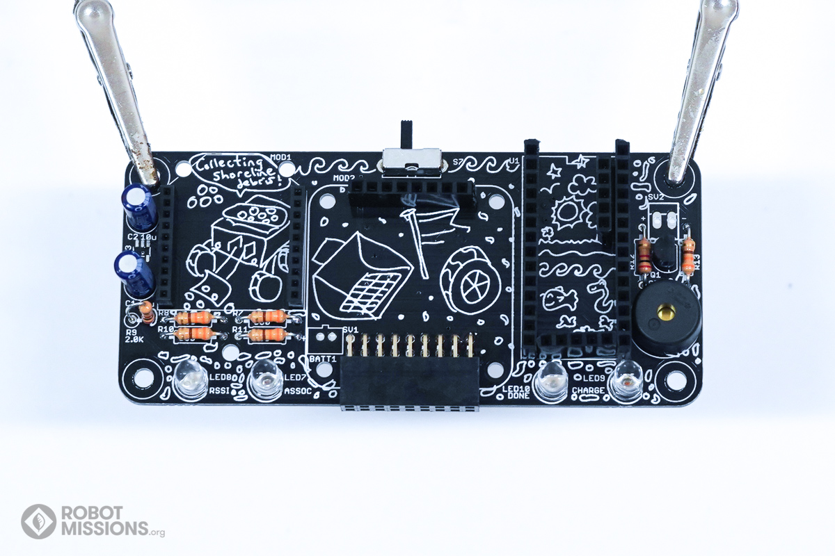
Obtain F headers for inserting into U1, which is where the Teensy 3.2 goes. Two rows of headers 14 pins are needed.
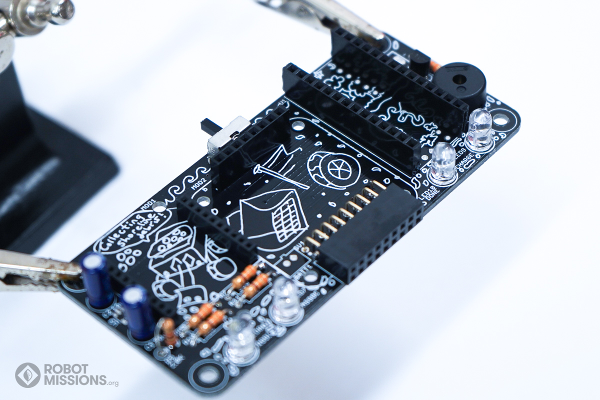
Here’s an angled view to show what those headers should look like.
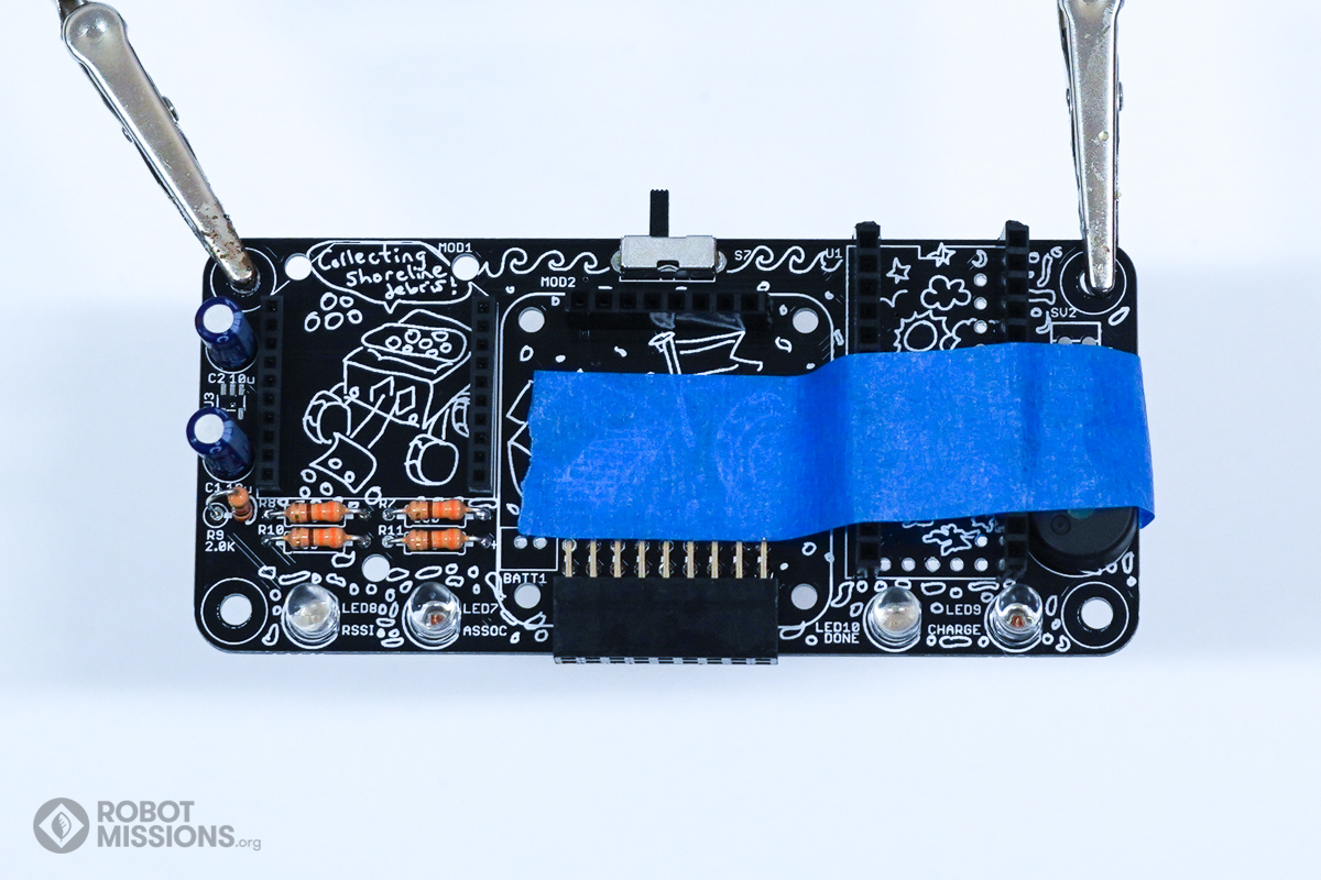
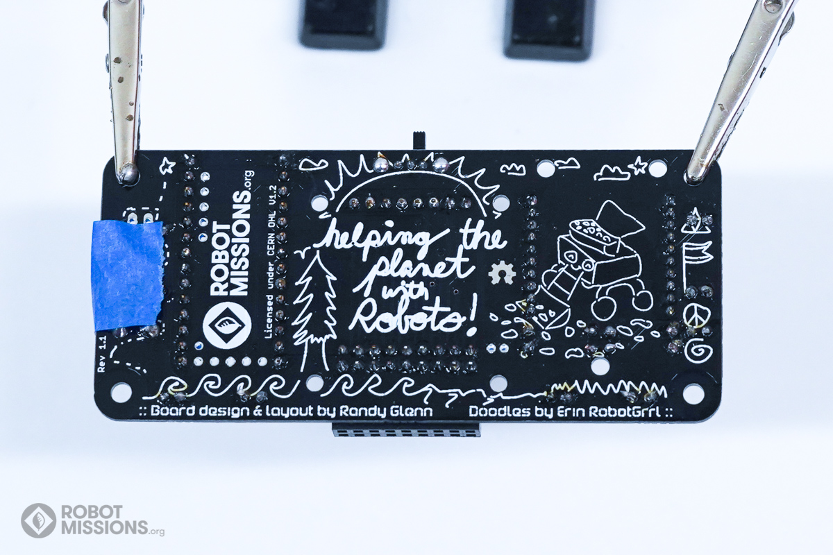
Apply tape to keep the headers in place. Then, flip the board.
Tack down one of the pads of each row with solder. This will make it easier to position. Then, relow as needed and position the headers so they are flush and perpendicular with the circuit board.
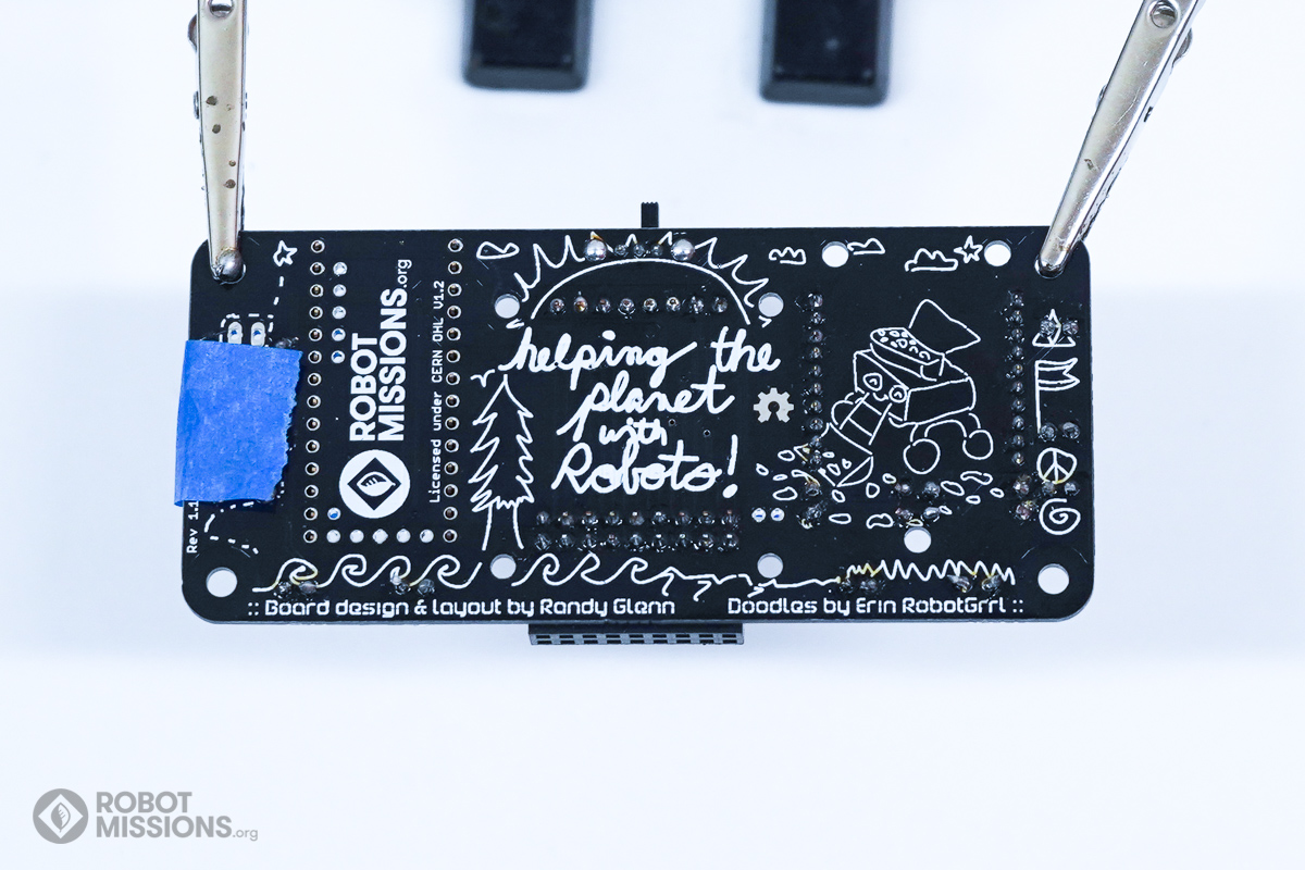
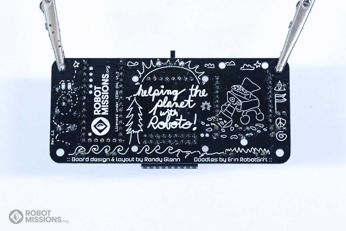
Solder the remainder of the header pads. When complete, flip the board.
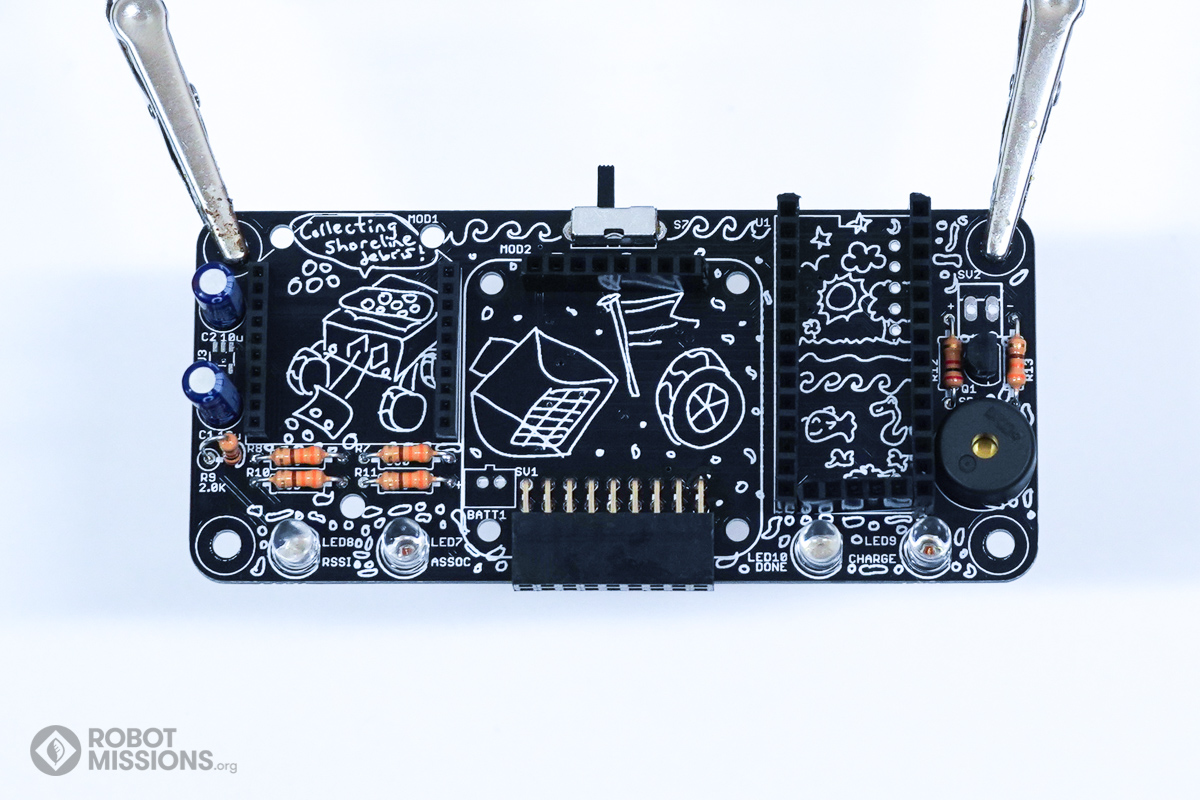
Insert a 5 pin F header at the bottom of U1 for the Teensy 3.2. You may need to trim some of the sides with an xacto knife. This way, it can be insert in between the two headers easily.
The top surface of this header must be flush with the other two headers.
The top surface of this header must be flush with the other two headers.
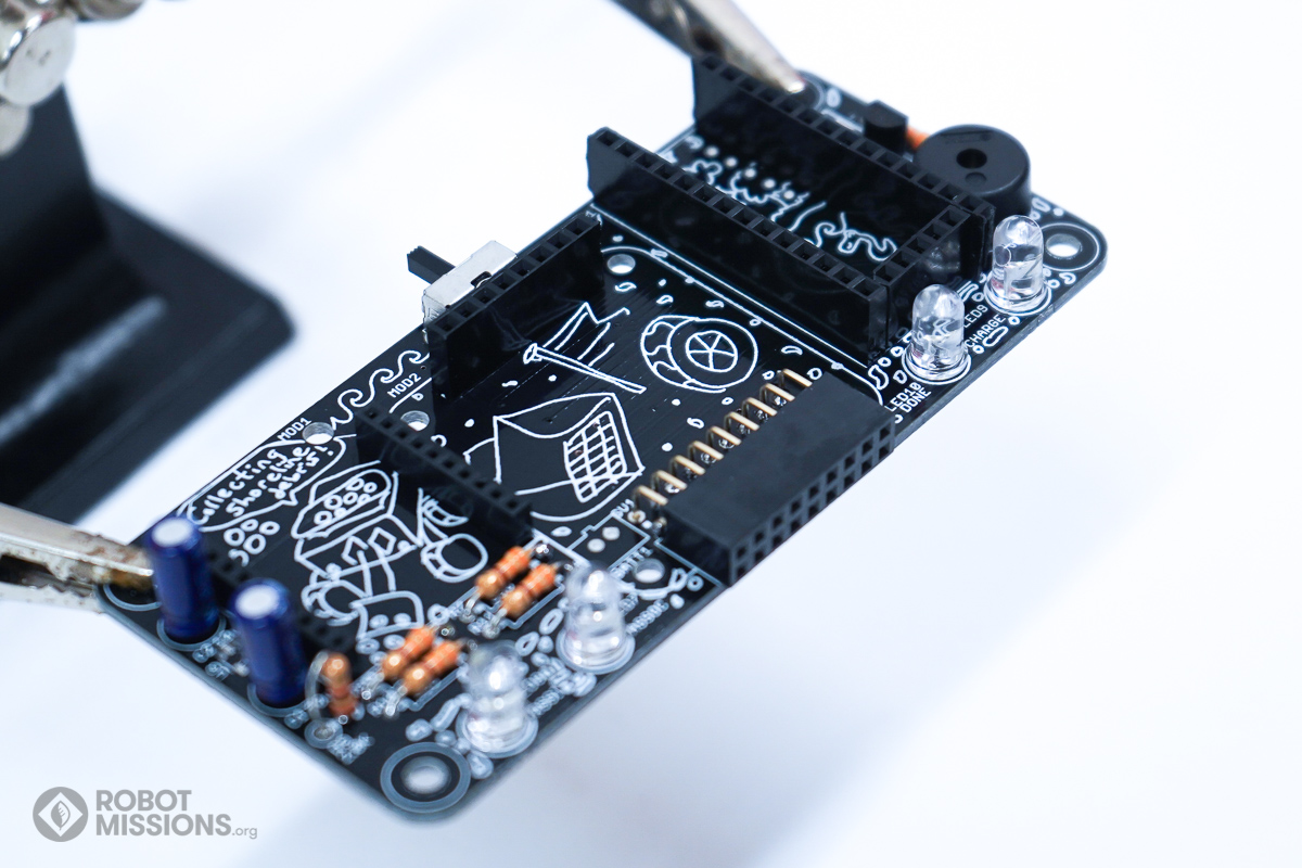
Here’s an angled view to show the header in its position. Ensure the header is attached, apply tape if needed, then flip the board.
Tack down one of the pads of the header with solder. This will make it easier to position. Then, relow as needed and position the header so it is flush and perpendicular with the circuit board.
Solder the remainder of the switch pads. When complete, flip the board.
Insert a 5 pin F header at the side of U1 for the Teensy 3.2. The top surface of this header must be flush with the other two headers.
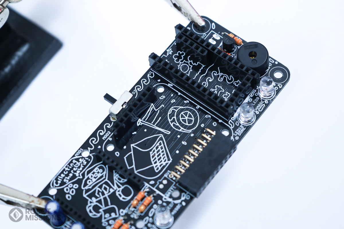
Here’s an angled view showing the header to be inserted.
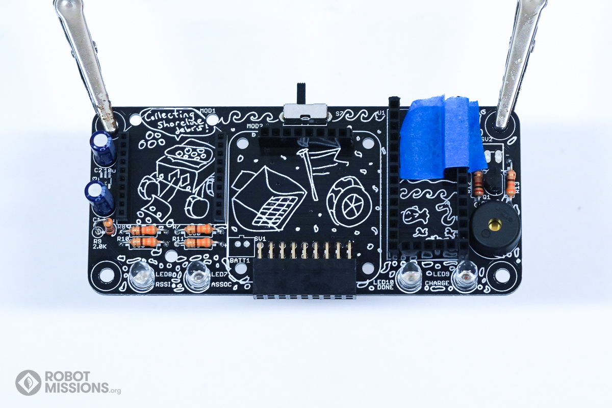
Apply tape to hold the headers in place when flipping the board. Then, flip the board.
Ensure the headers are flush with the board after flipping. Using your soldering iron, apply solder to the pads of the header. Then, flip the board.
| ← Headers, headers, headers | Teensy preparation → |