The much anticipated part! Inserting the buttons into the keypad! Enjoy the clickiness of these buttons. For this part you will need the 6 buttons, as well as the 2 row 18 pin M header.
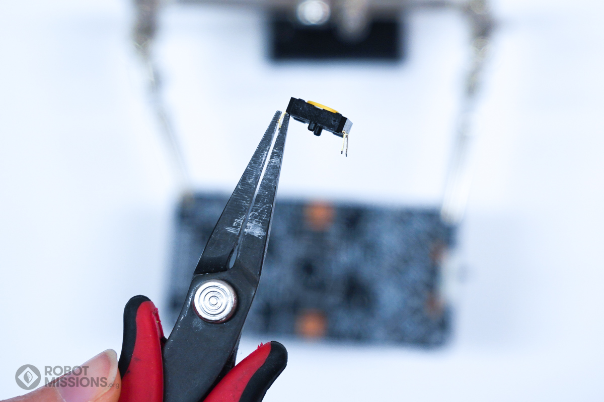
Time for the buttons! In order to prepare the buttons, use needlenose pliers to straighten out the bends in the switch’s pins. This needs to be done to all 4 pins for all 6 buttons.
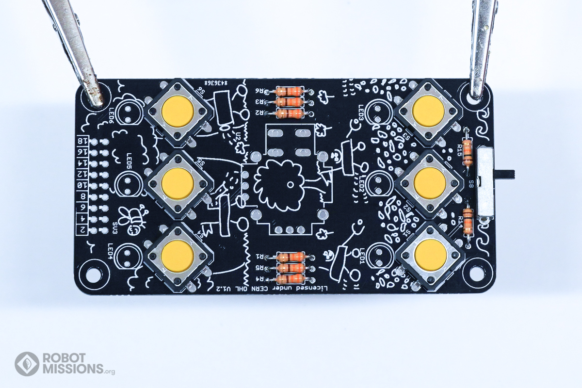
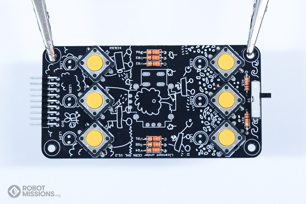
Insert all 6 buttons into the switch locations, S1, S2, S3, S4, S5, S6. The orientation does not matter, however all of the pins from the switch need to be inserted through a hole. Ensure the pin protrudes to the other side of the circuit board.
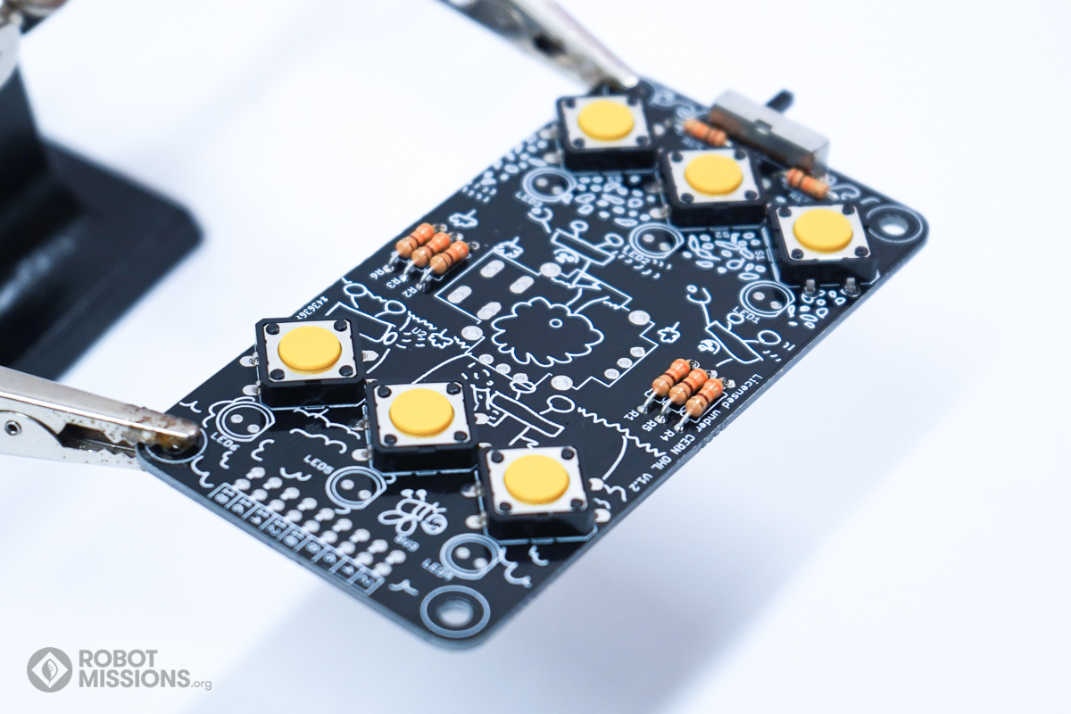
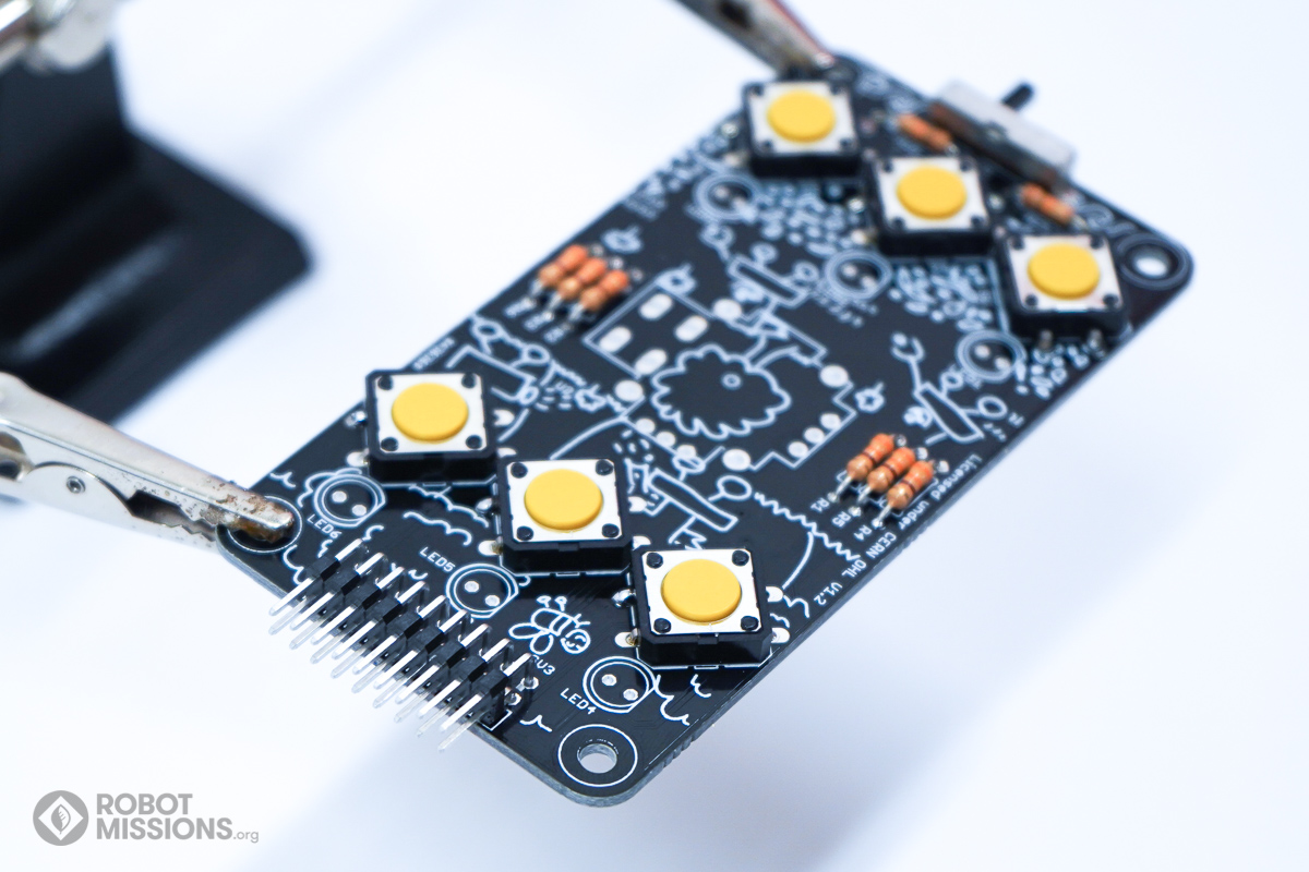
Here is what the buttons should look like as viewed from an angle. Ensure each button is flush with the circuit board.
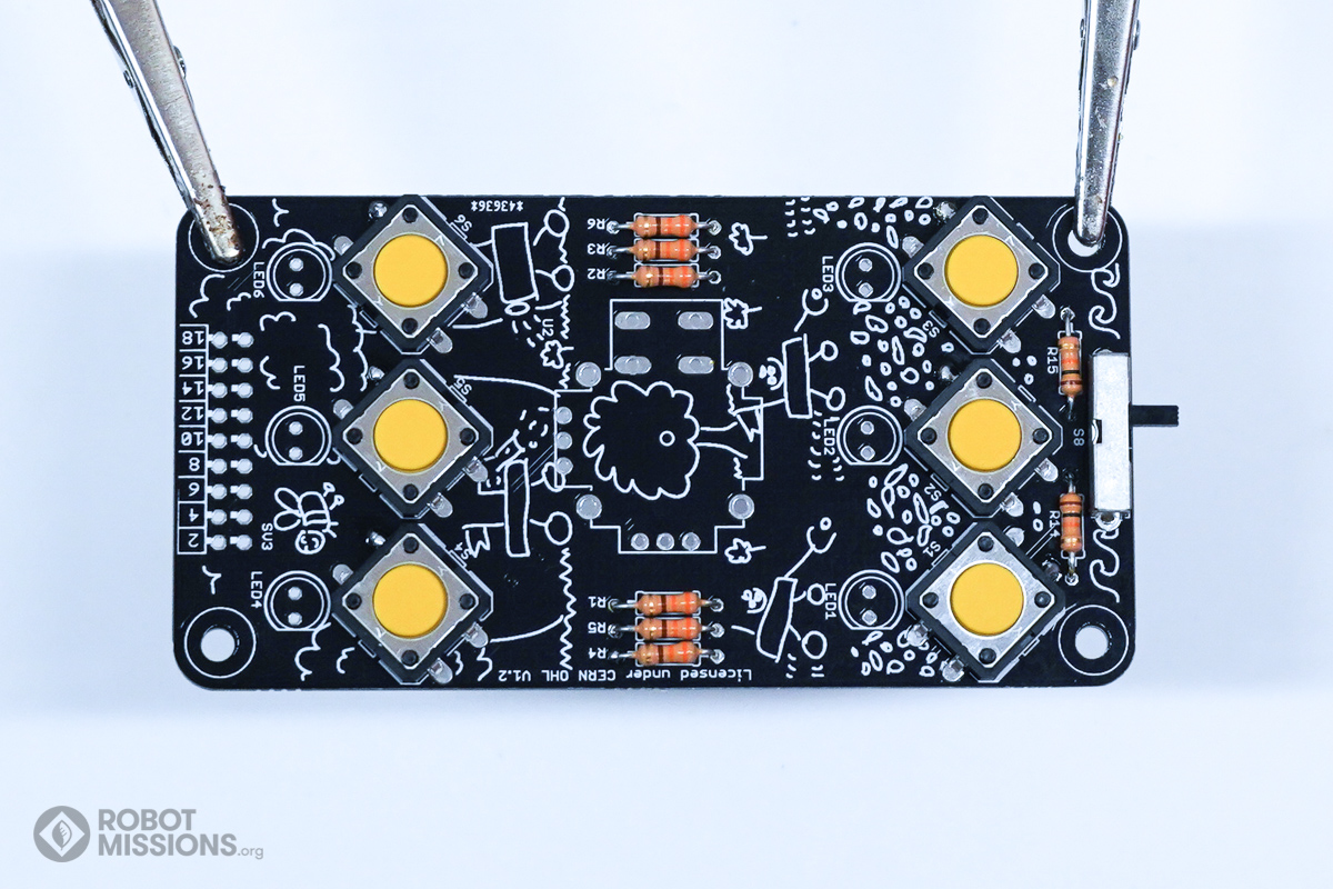
Tack down one of the pads with solder first before flipping. This will make it stay in place a bit easier. Then, flip the board.
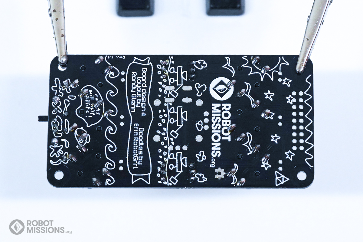
Using your soldering iron, solder the pads of the buttons. Then, flip the board.
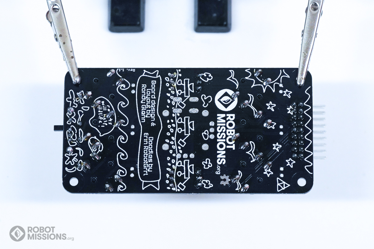
Obtain the 2 row 18 pin M header. Insert it into SV3. The pins from the header should be facing outwards to the upper edge of the keypad circuit board.
Here is a look at the orientation the 2 row 18 pin M header should be in. Ensure the header is flush and perpendicular with the board. Tack down one of the pins with solder and using your soldering iron to help keep it in place. Then, flip the board.
Using your soldering iron, solder the pads of the header. Then, flip the board.
| ← Mode switch and resistors | LEDs for the keypad → |