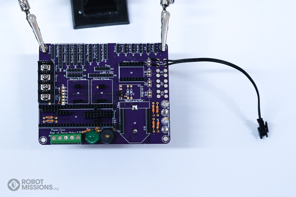
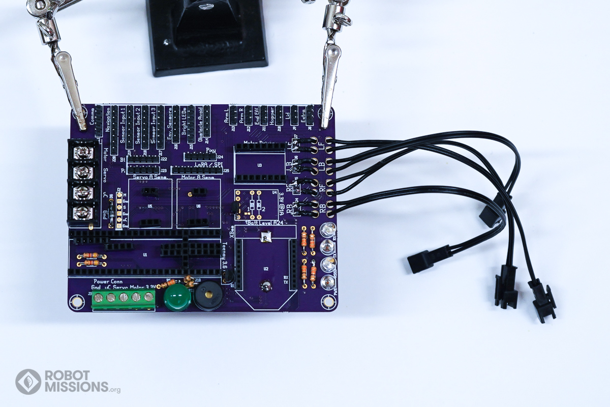
In this section we are adding the motor connectors. These are special JST-SM connectors that are attached to the brain board through strain relief holes. The other end connects with the mating connector which is on the motor wires. These connectors can be quickly interchanged, if you want to change Bowie’s wheels during a Field Test. In this section you will need the 4 JST-SM connectors (M).
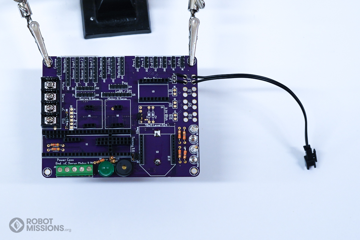
We’re going to dive in to this in the following steps, but the first two images are the quick summary of it if you want to jump ahead.
First, thread the connector in like this. Note the orientation of the connector. The clippy part faces up. This is important because we want to be consistent between different drive systems.
Apply solder to the two pads.
The next step is to pinch the wires down onto the pads, and apply the soldering iron to reflow the solder.
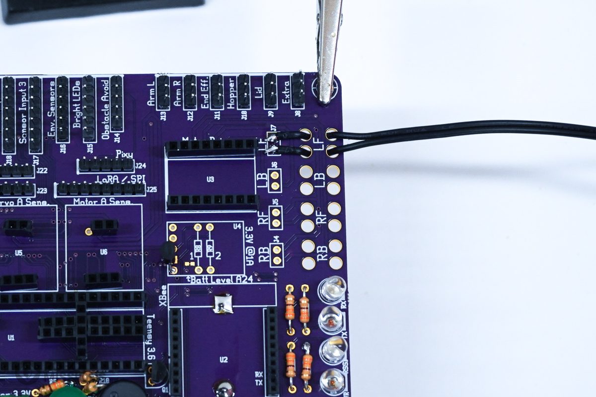
Here’s how to do it step by step. Orient the wire so the clippy part is facing up. Insert the wires through the set of holes closest to the edge of the board.
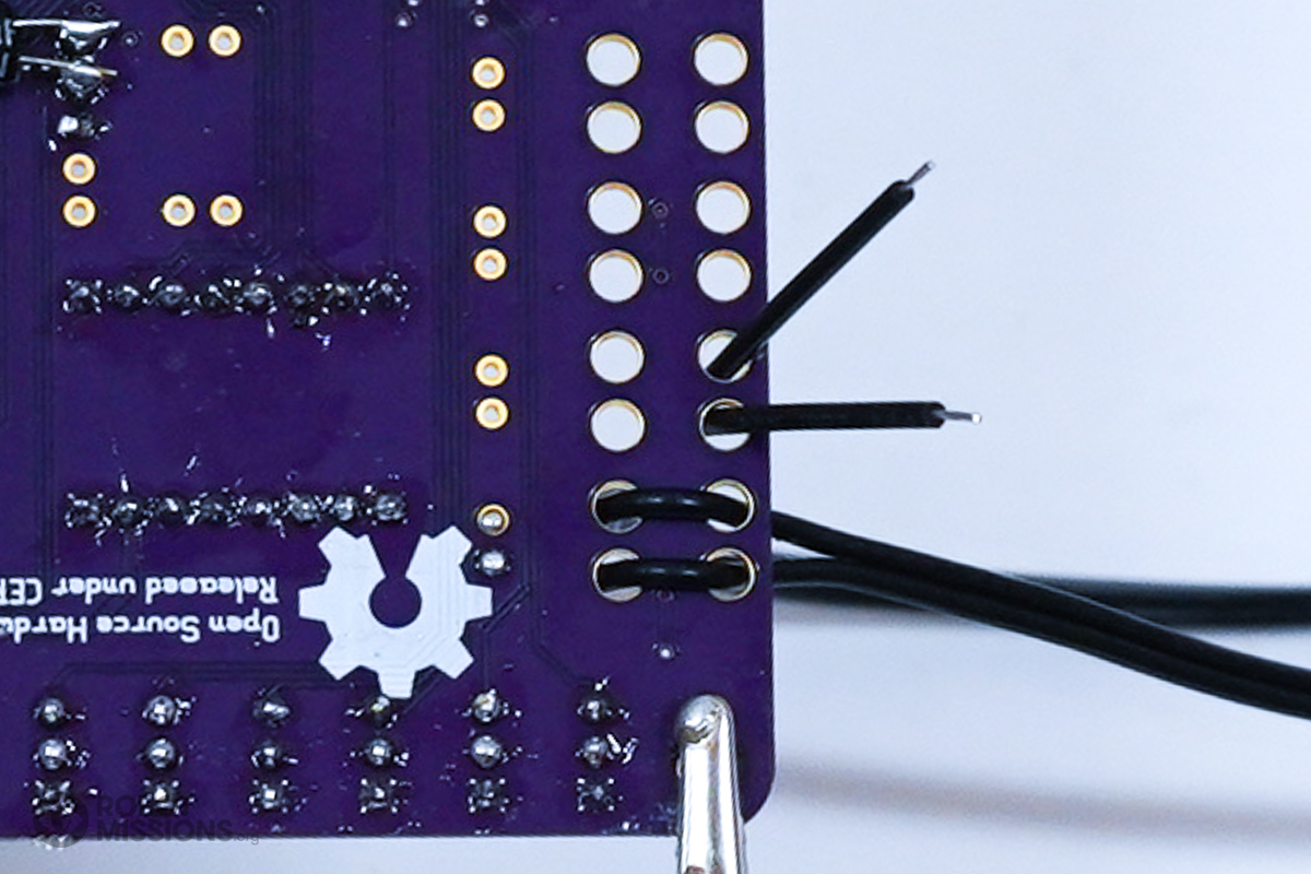
Flip the board over. Here are the wires.
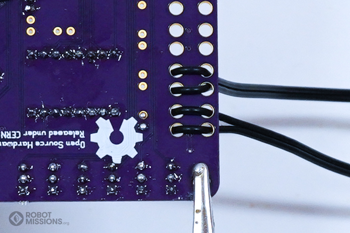
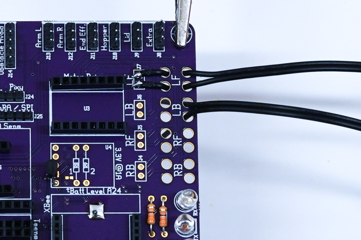
Now fold the wires over into the next set of holes.
Flip the board over. Here are the wires.
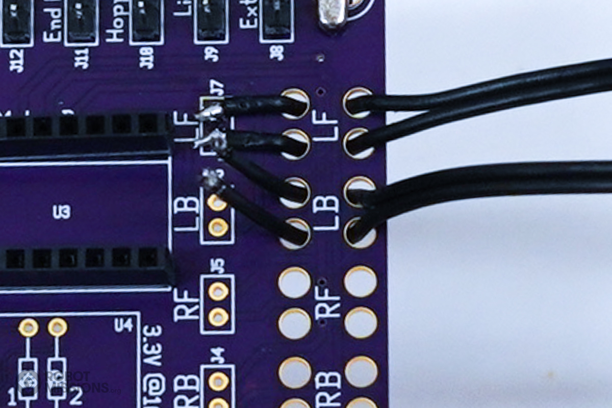
Apply solder to the wires and pads.
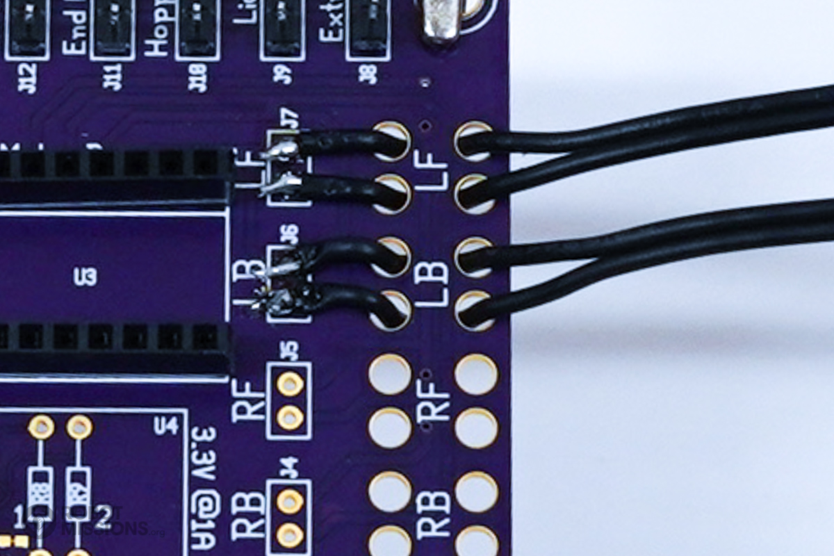
Solder the wires to the pads.
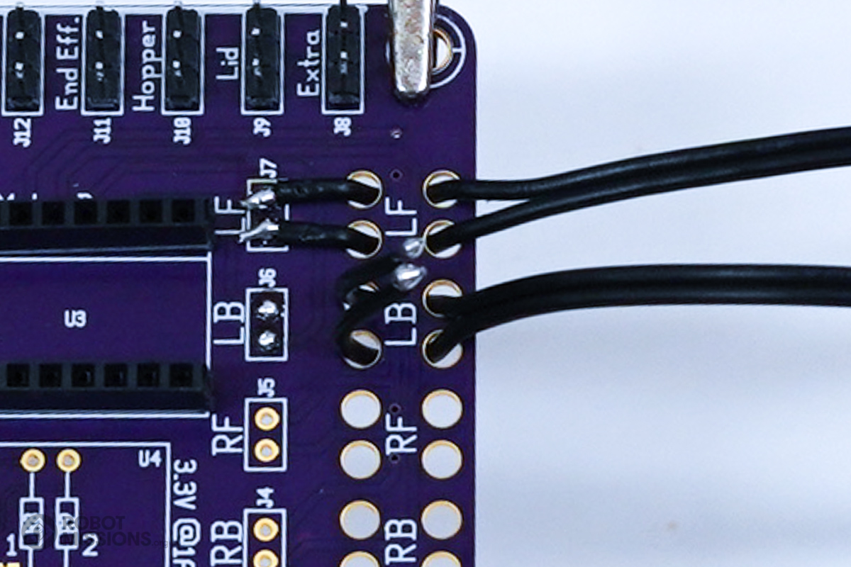
Now repeat the process for the remainder of the wires.
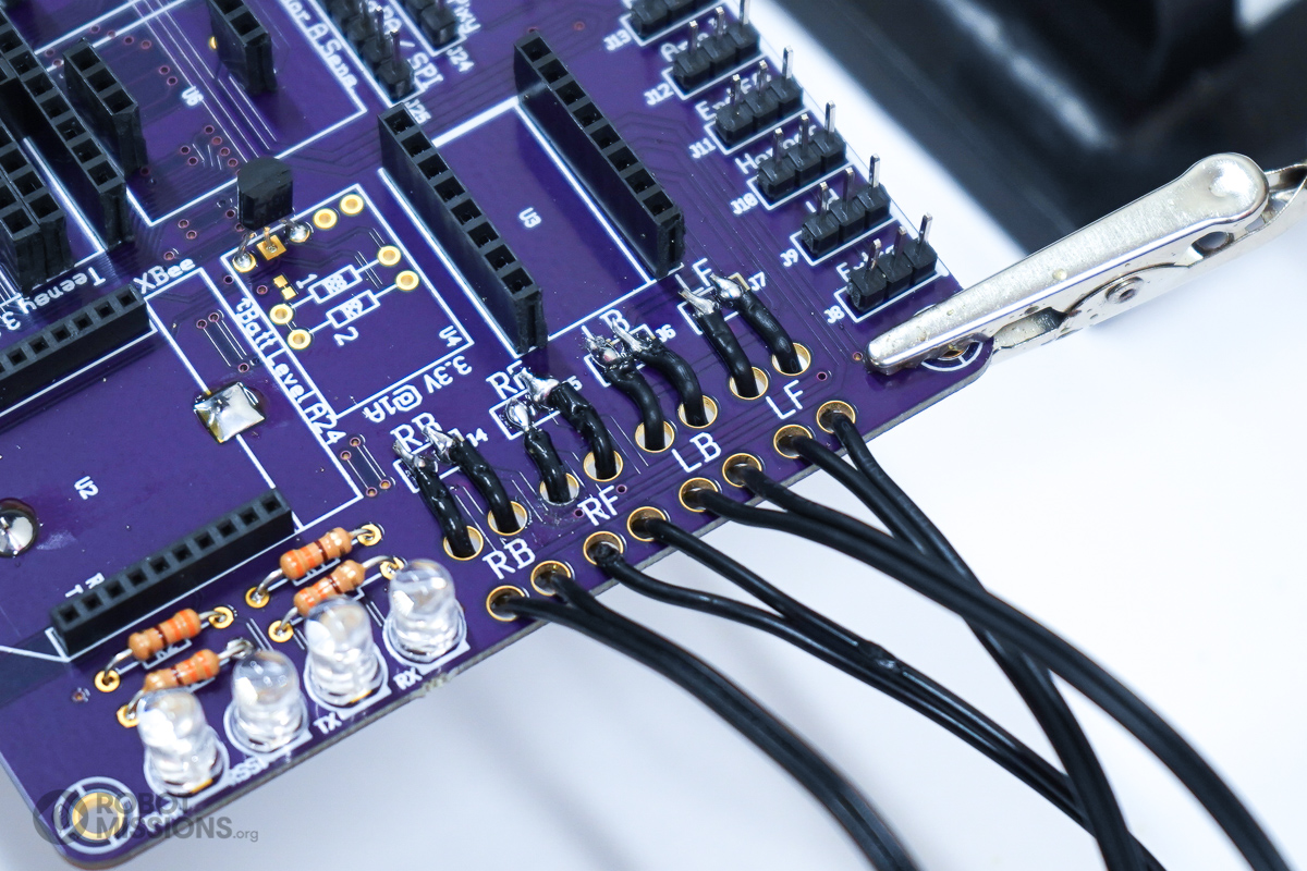
Here are all the wires, and they are soldered.
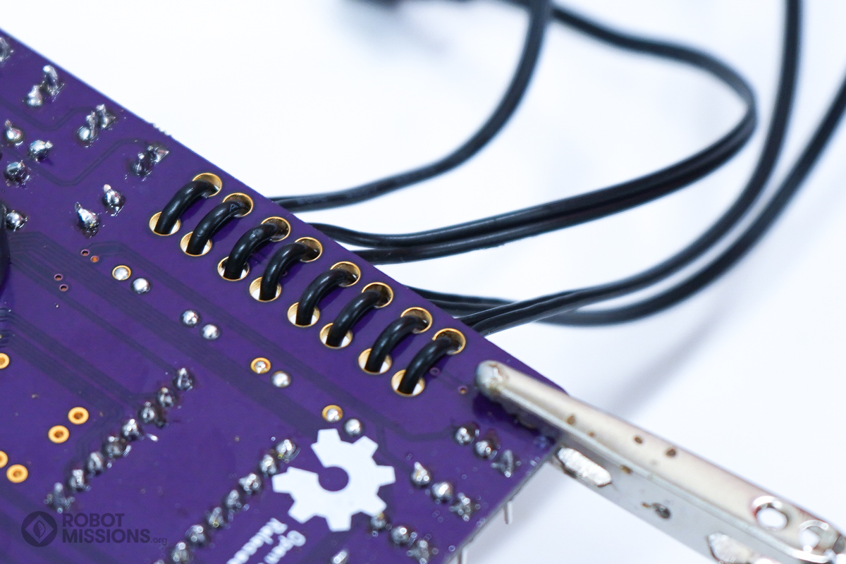
On the flipside of the board, here are all the wires through the strain relief holes.
| ← Headers – M | Motor and current headers – M → |