In this part we will be soldering the wires to the voltage regulators. The smaller regulator is what will supply the voltage to the Bowie Brain, or whichever controller you are using. The larger regulator is what will supply the voltage to the motors – both DC and servo. Rest assured, the wires are of thick enough gauge to handle the current. For this, you will need both regulators, and access to the wires that were cut in the previous step.
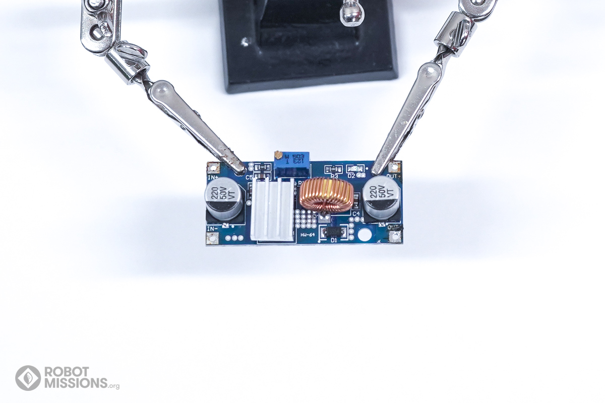
Start first with the smaller voltage regulator. This one can output at 5A. Yours may not look exactly the same, this is okay, the steps will guide you through. This is used to supply voltage to the brain board and sensors.
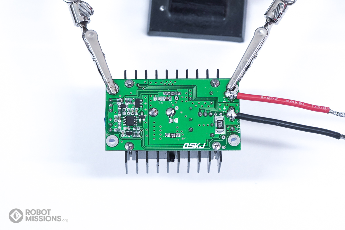
The first task to get started with is to add solder to the IN+ pad.
Now solder a positive wire to it, corresponding to letter C.
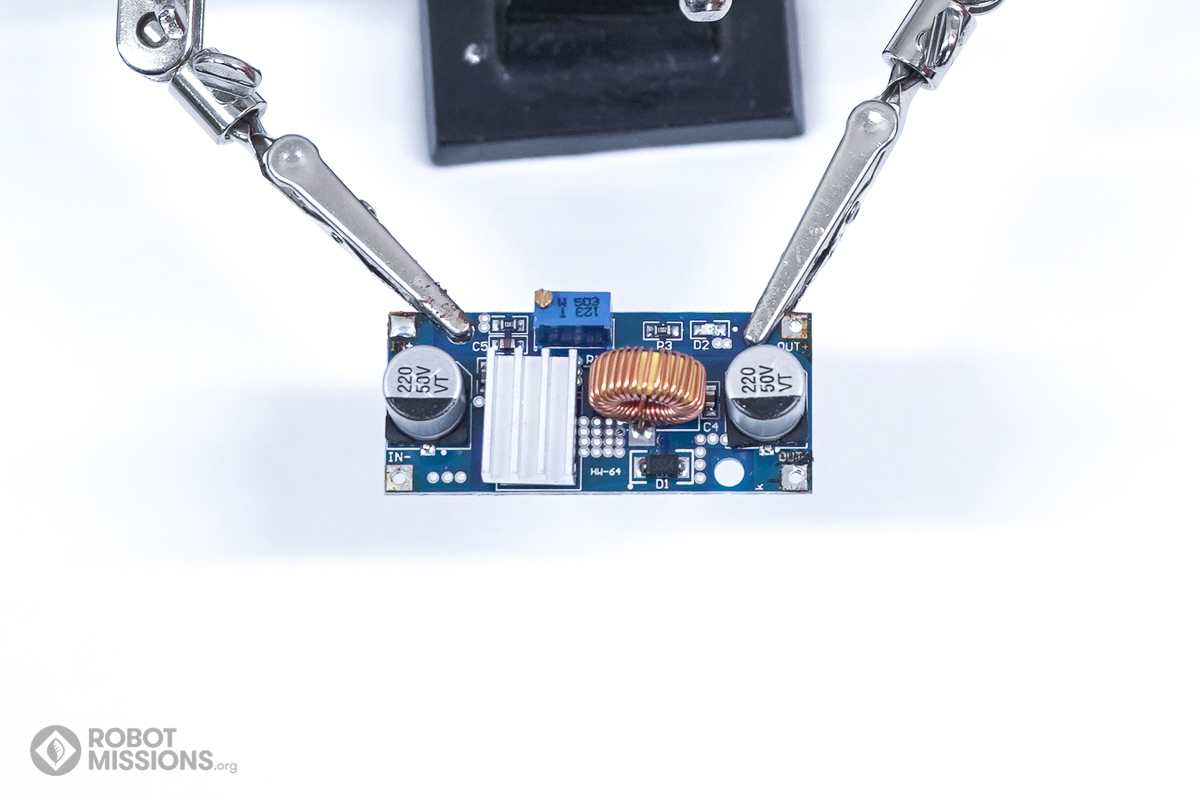
Add solder to the IN- or GND pad on the same edge of the board as previous.
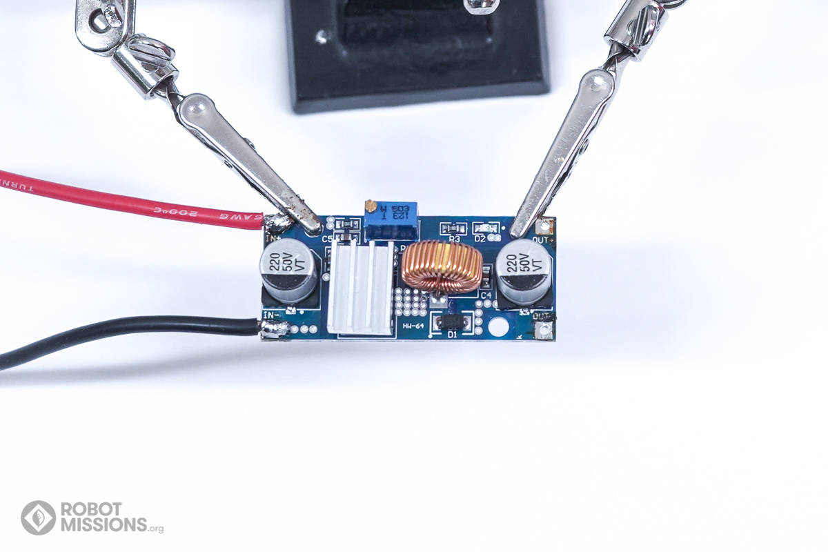
Now solder a negative wire to it, corresponding to letter (D).
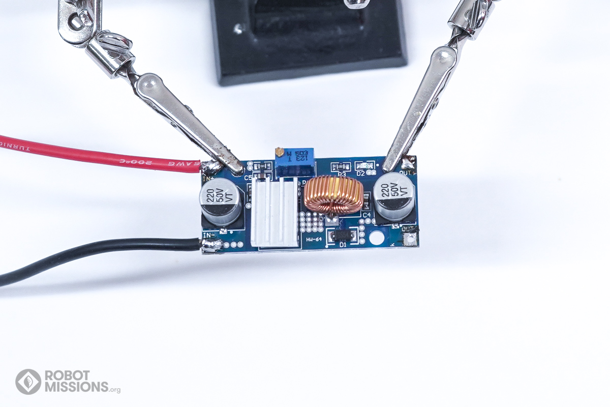
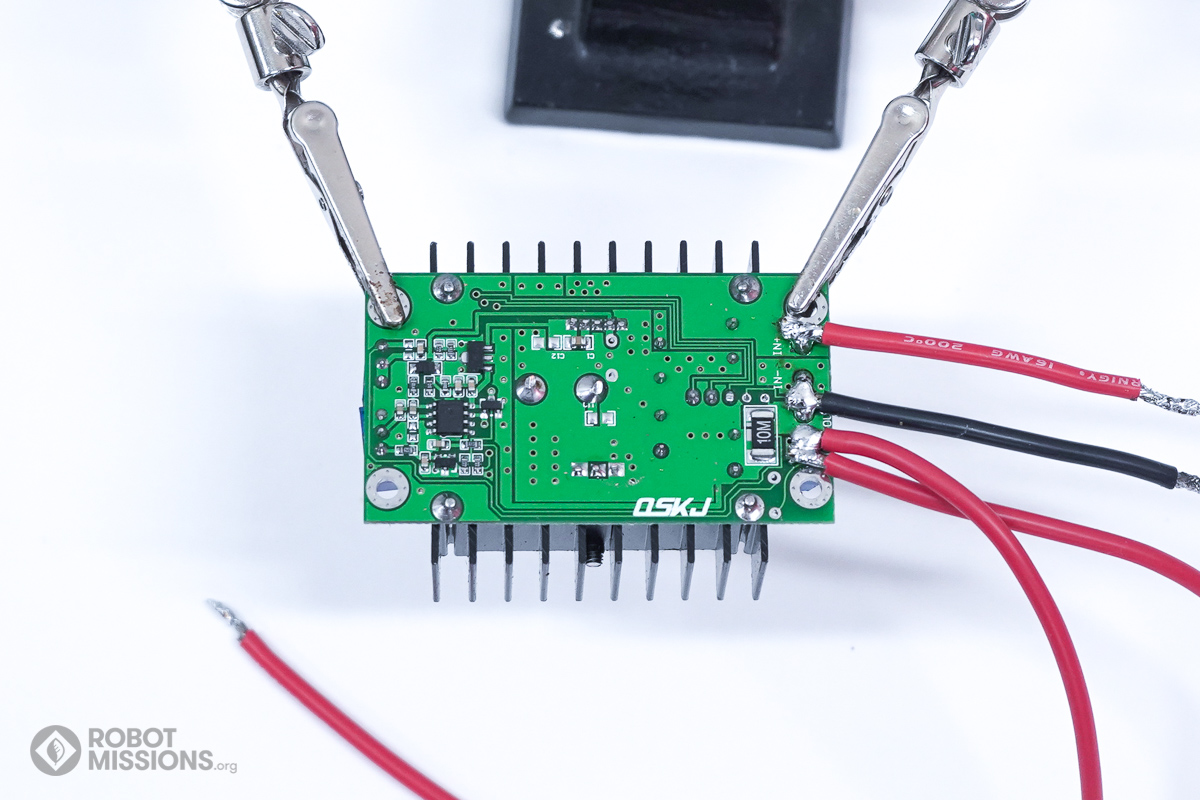
Add solder to the OUT+ pad on the opposite edge of the board.
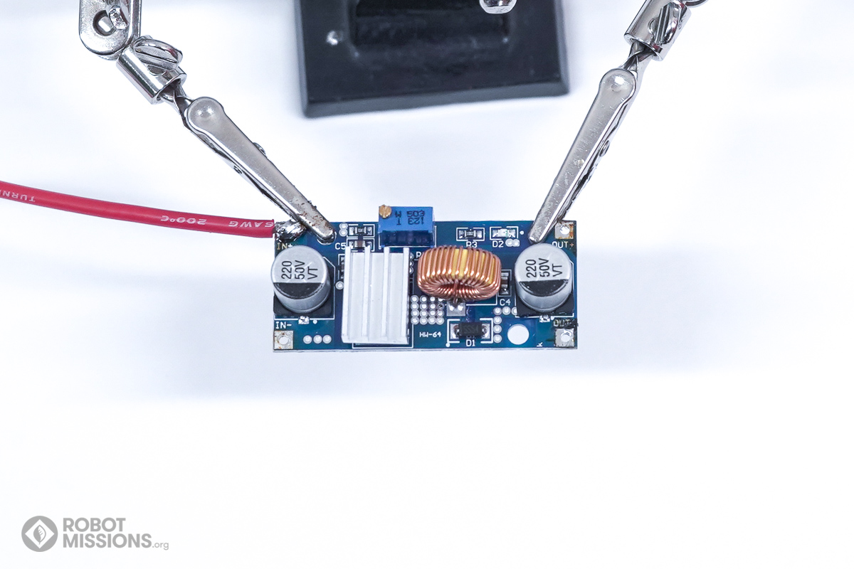
Now solder a positive wire to it, corresponding to letter (G).
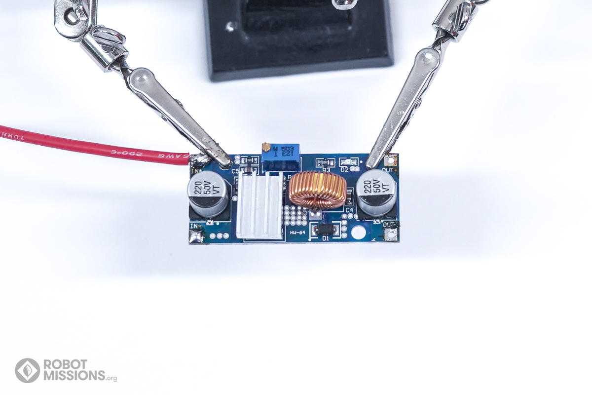
This is what the voltage regulator should look like now.
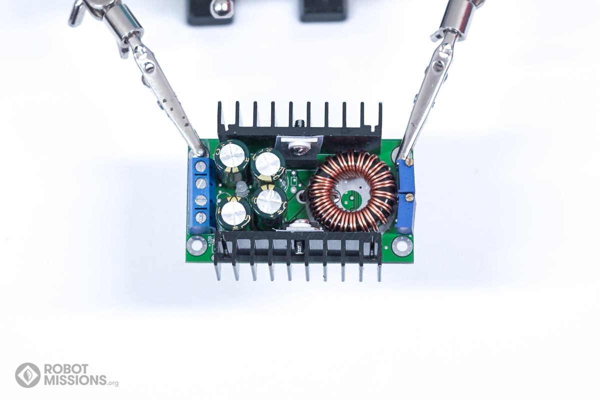
Now obtain the larger voltage regulator. This one can output 8A. Yours will likely look quite similar to this one. This is used to supply voltage to the DC motors and servo motors.
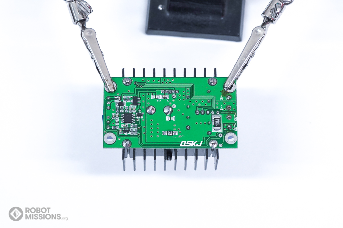
Flip the regulator over.

Add additional solder to the IN+ pad.
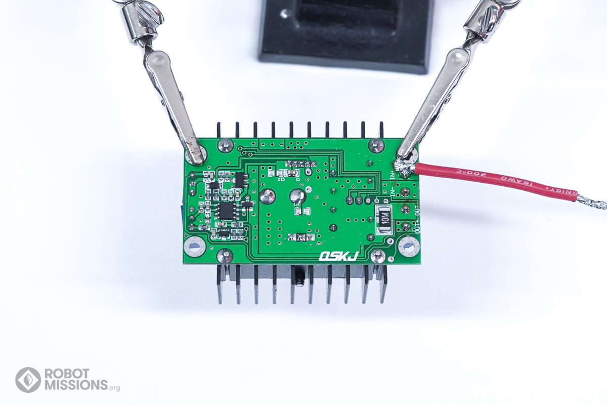
Solder a positive wire to it, corresponding to letter (E).
Solder the two IN- and OUT- pads together. These are both – so it is ok.
Solder a negative wire to it, corresponding to letter (F).
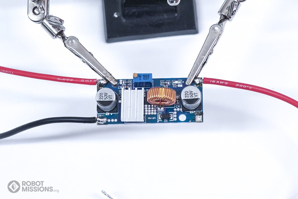
Add solder to the OUT+ pad. This time, solder two positive wires to it, corresponding to letters (I) and (H).
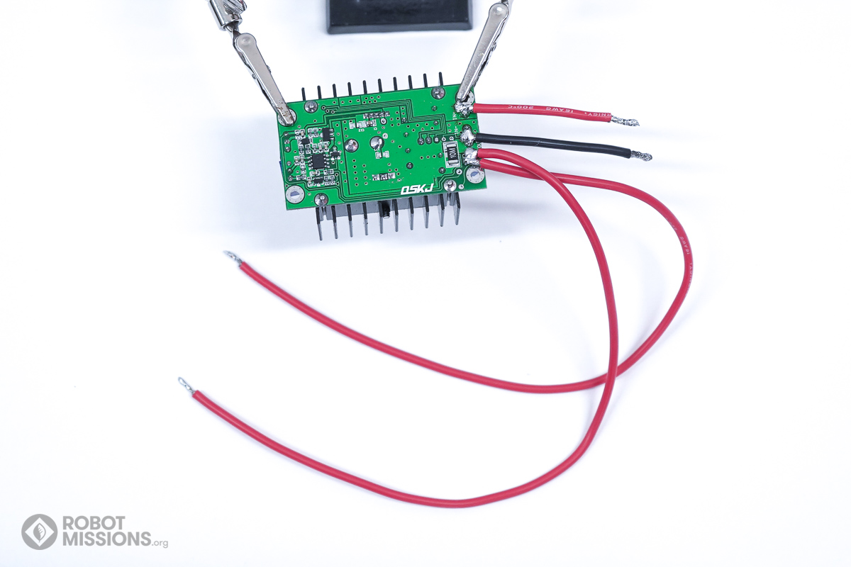
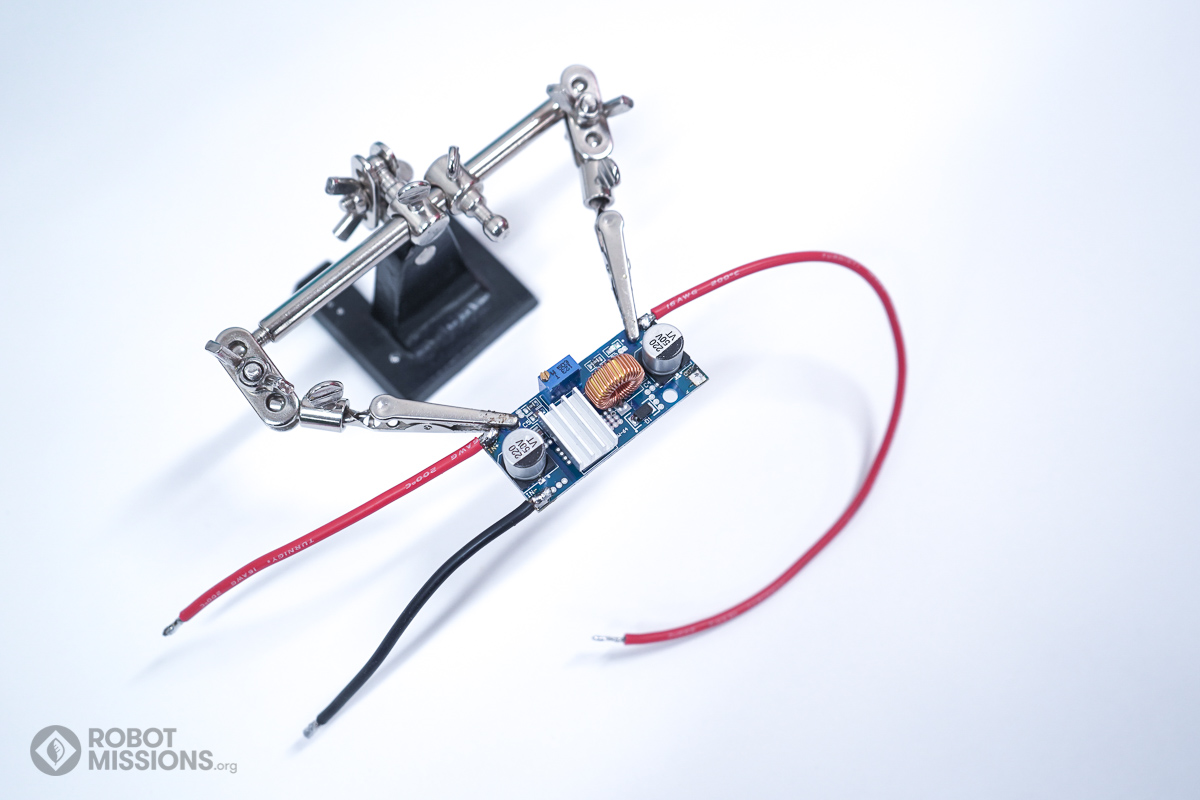
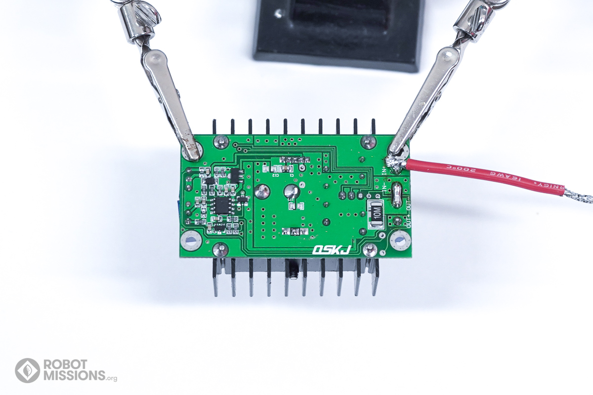
This is what the voltage regulator should look like now.
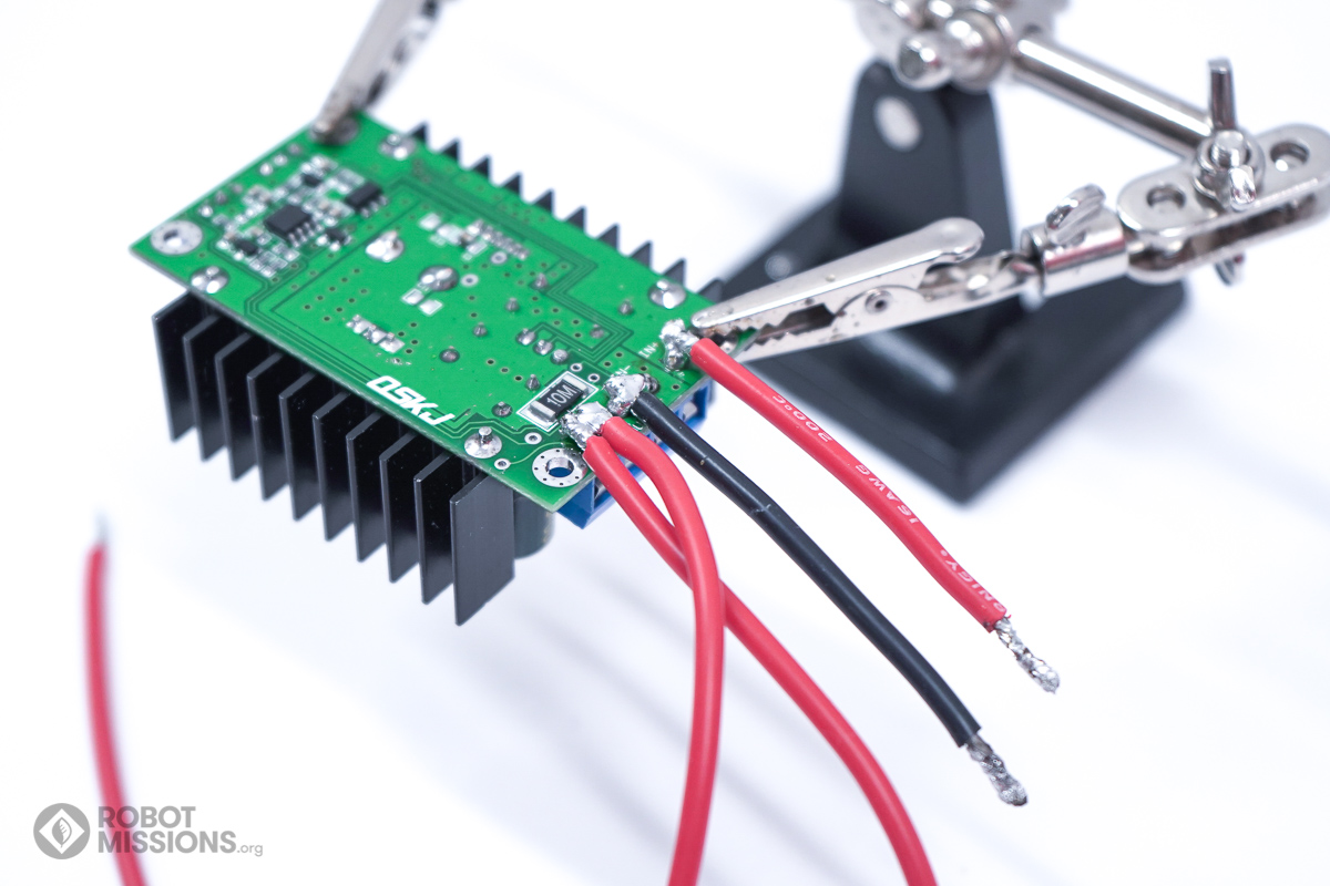
Here is a closer look at how the wires should be soldered to the voltage regulator. Take care to check for any accidental bridges of solder.
| ← Introduction | Batt connector and a bit of enclosure → |