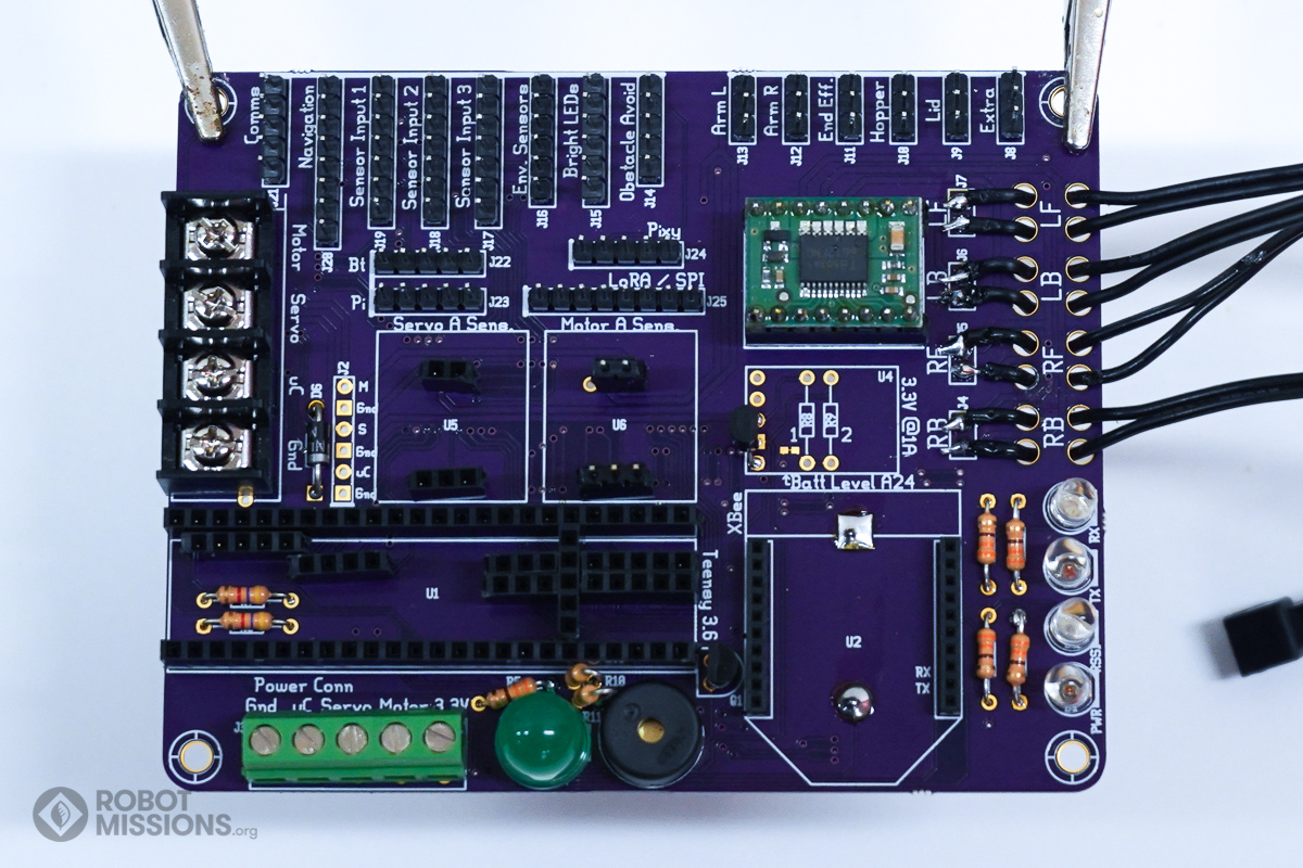
In this section we are adding the M headers which will be soldered to the breakout boards for the motor driver and current sensors. It will be important to note the orientation of the boards. In this section you will need M headers, the motor breakout board, and the 2 current sensor boards.
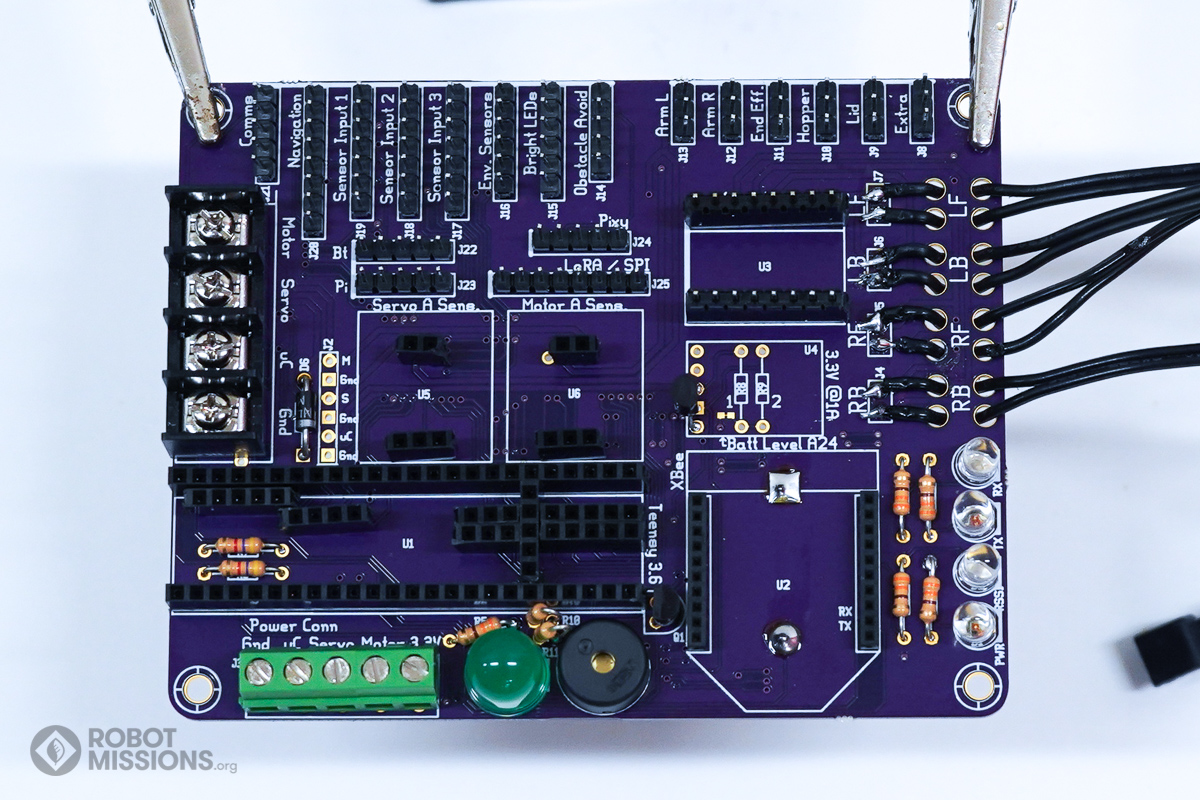
Cut the M headers to the proper length for the motor headers in U3. There will be 2 rows with 8 pins.
Insert them into the F headers in U3.
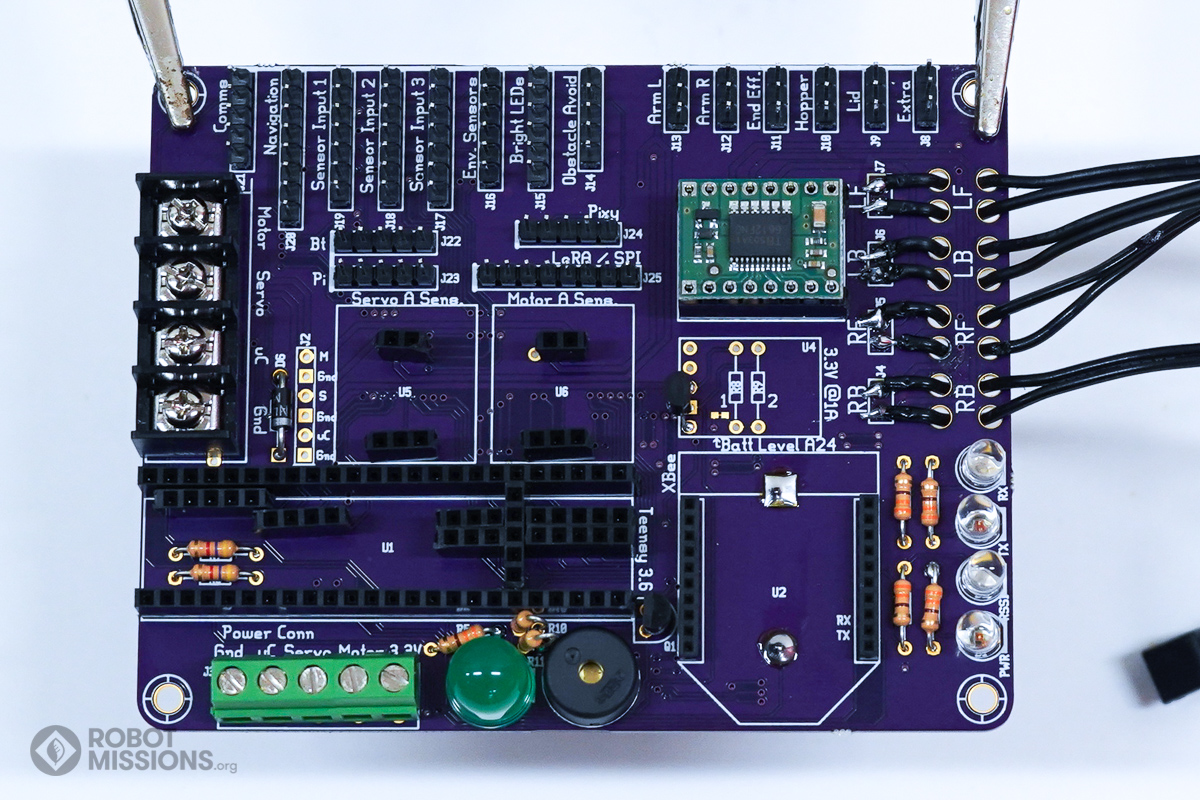
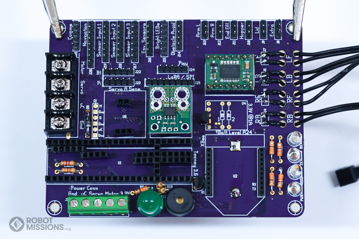
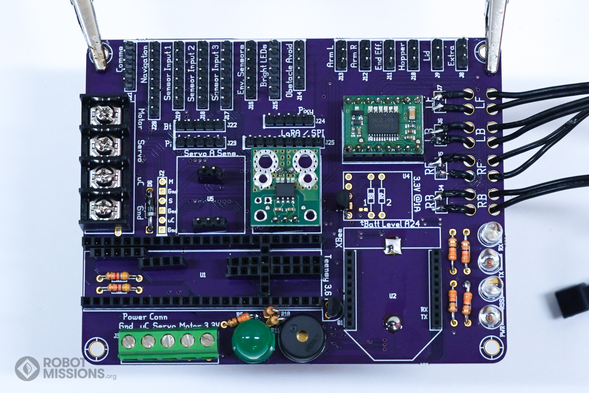
Add the motor driver board onto the M headers. Notice the orientation of the board. The chip side is up. The edge with the two square pads will be to the left. This represents to pads that are both Gnd. This orientation can be double checked by looking at the flip side of the motor breakout board.
Ensure the motor breakout board is flush. Solder the headers to the pads.
Here is the motor breakout board soldered to the headers.
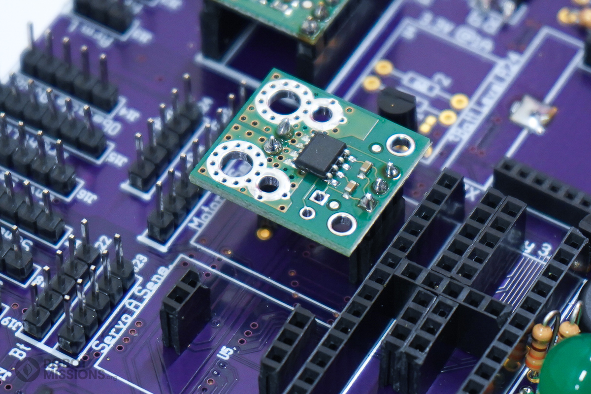
Cut the M headers to the proper length for the current headers in U6. There will be 2 rows with 2 pins and 3 pins.
Insert them into the F headers in U6.
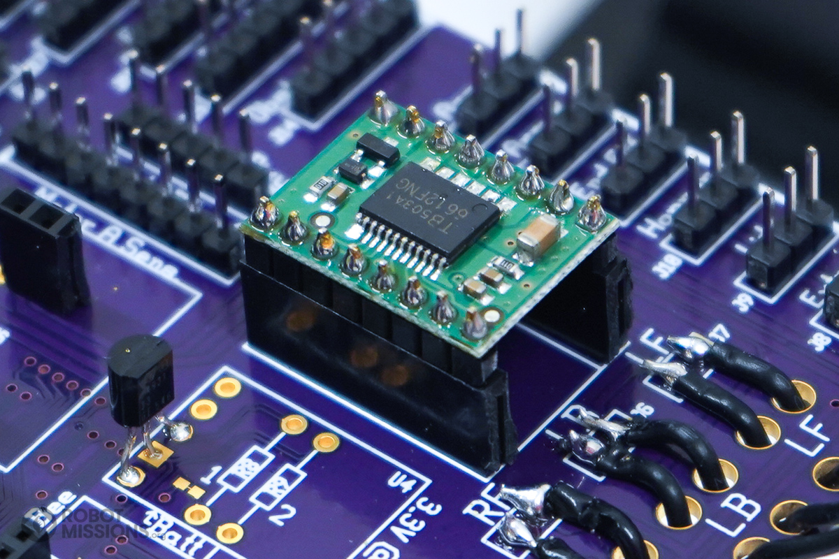
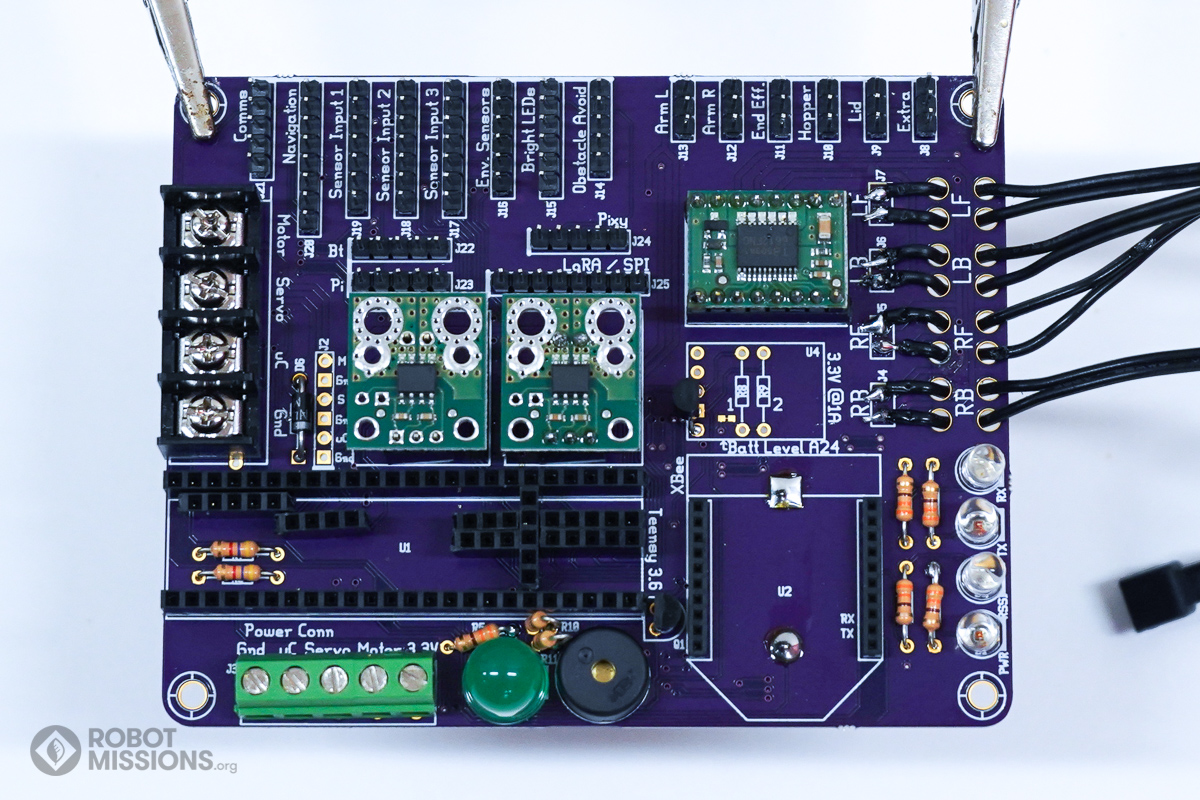
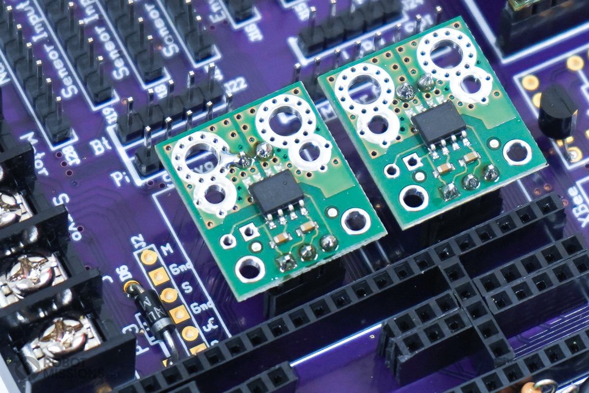
Add the current driver board to the M headers. Notice the orientation of the board. The chip side is up. The three pin header will be at the bottom edge of the current driver board. This orientation is less easy to confuse, as it is not symmetrical.
If your sensor now has 5 pins, it is still compatible with this – line up the 3 pins with the corresponding 3 pins in the middle.
If your sensor now has 5 pins, it is still compatible with this – line up the 3 pins with the corresponding 3 pins in the middle.
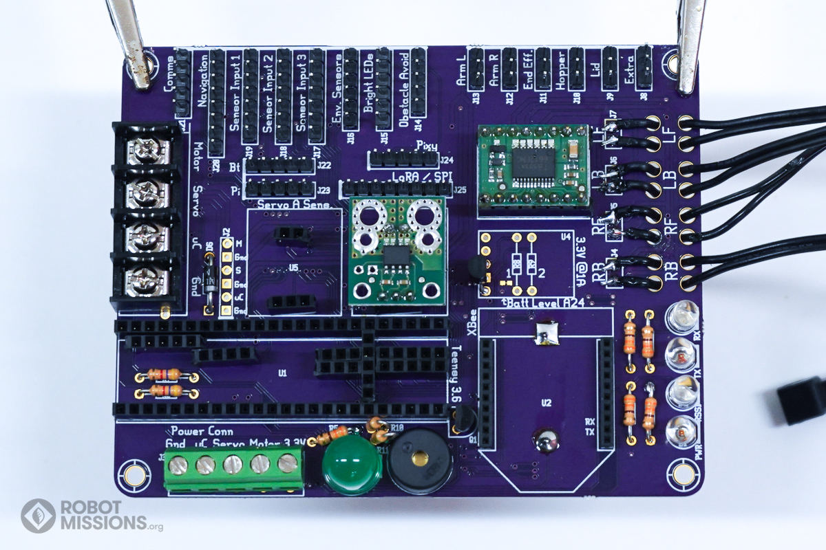
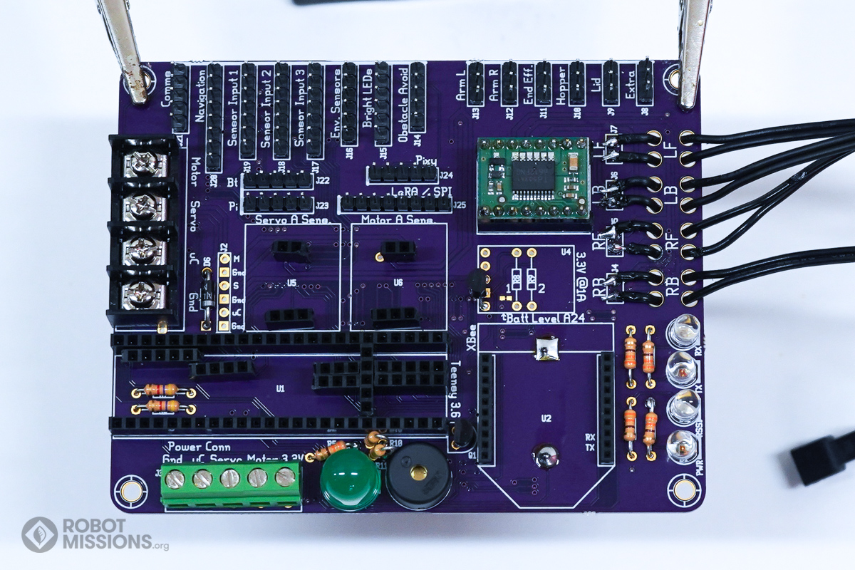
Ensure the current sensor board is flush. Solder the headers to the pads.
Here is the current sensor board soldered to the headers.
Same thing, but for the other current sensor.
Cut the M headers to the proper length for the current headers in U5. There will be 2 rows with 2 pins and 3 pins.
Insert them into the F headers in U5.
Add the current driver board to the M headers. Notice the orientation of the board. The chip side is up. The three pin header will be at the bottom edge of the current driver board. This orientation is less easy to confuse, as it is not symmetrical.
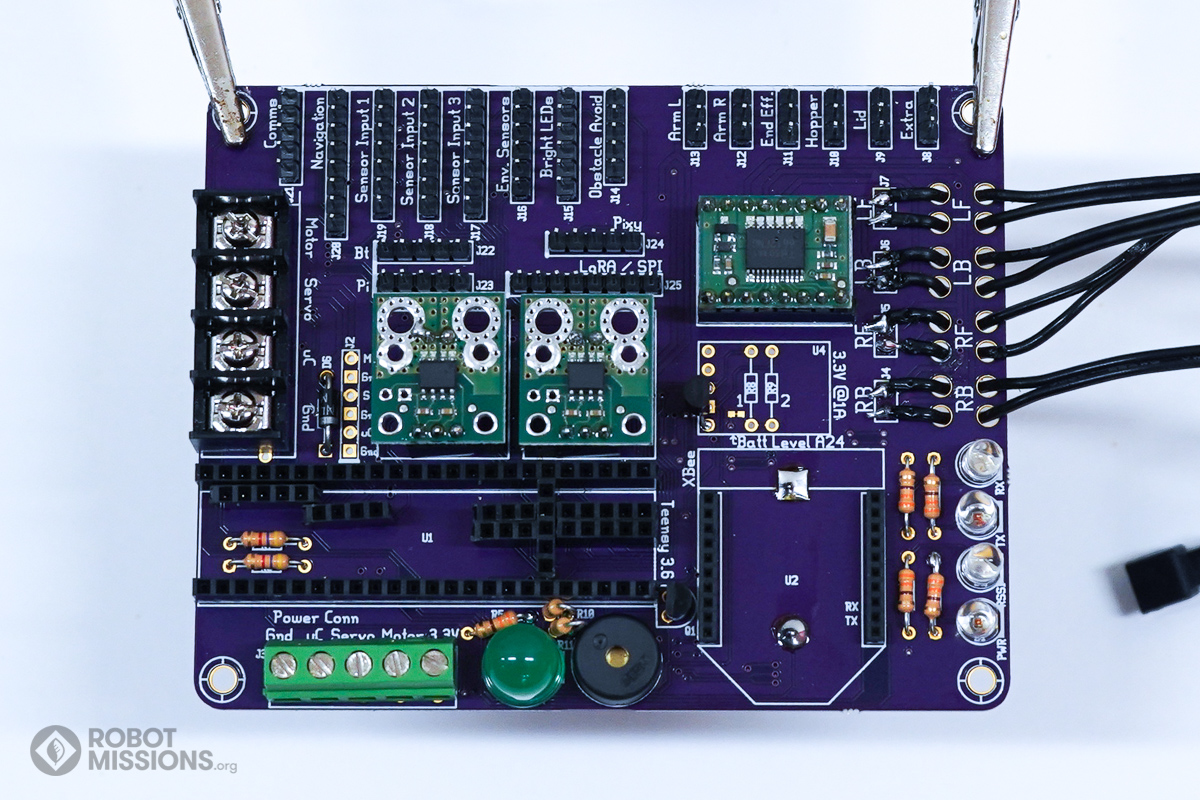
Ensure the motor breakout board is flush. Solder the headers to the pads.
Here is the current sensor board soldered to the headers.
| ← Motor connectors | Everything Teensy 3.6 → |