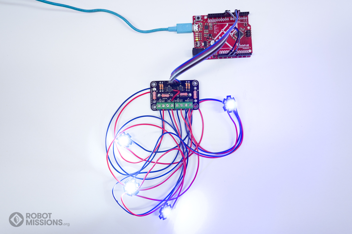
In this part we will get to see the much awaited for moment of the first illumination of the LEDs. Using an Arduino or similar, run a test program to verify all connections are OK and that all of the soldering is OK. For this part you will need an Arduino, its usb cable, jumpers, and your computer to program it.
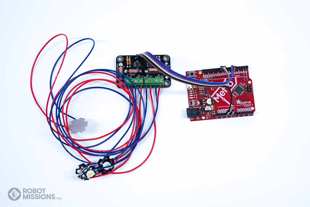
Following the connections on the header on the super bright lights board, make the following connections:
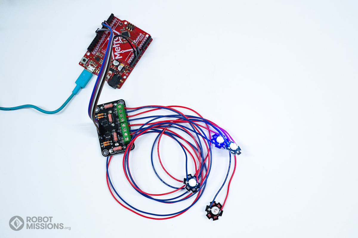
Gnd -\> Gnd on the Arduino
+5V -\> 5V on the Arduino
1 -\> Pin 9 on the Arduino
2 -\> Pin 10 on the Arduino
3 -\> Pin 5 on the Arduino
4 -\> Pin 6 on the Arduino
*Note: In this photo we used F-M jumpers. If you have additional solid core wire, that can be used as a makeshift way to turn F-F jumpers to F-M. We included F-F headers as this allows for an easier connection to the Bowie Brain.
In the case of this photo, we determined the problem was with a circuit board mistake. This has since been fixed, and this problem is not the case your your kit with the new circuit boards.

| ← Wires to the LEDs | Enclosures to protect → |