by Erin RobotGrrl | Dec 13, 2020 | News, Tech Logs
Basic blinking is done. It works! The analog value from the temperature sensor is received on serial monitor. Will need to remember in the future to go back and look at the actual formula used in the datasheet to go from this value to one in degrees Celsius. Before printing the pieces, work will have to be done on the 3D printer since it is experiencing an issue at some places on the build platform. Next step is back to the software, getting the AR draggable functionality working and ready to be merged with MQTT. Summary post is up on Patreon
here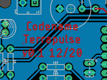
by Erin RobotGrrl | Dec 11, 2020 | News, Tech Logs
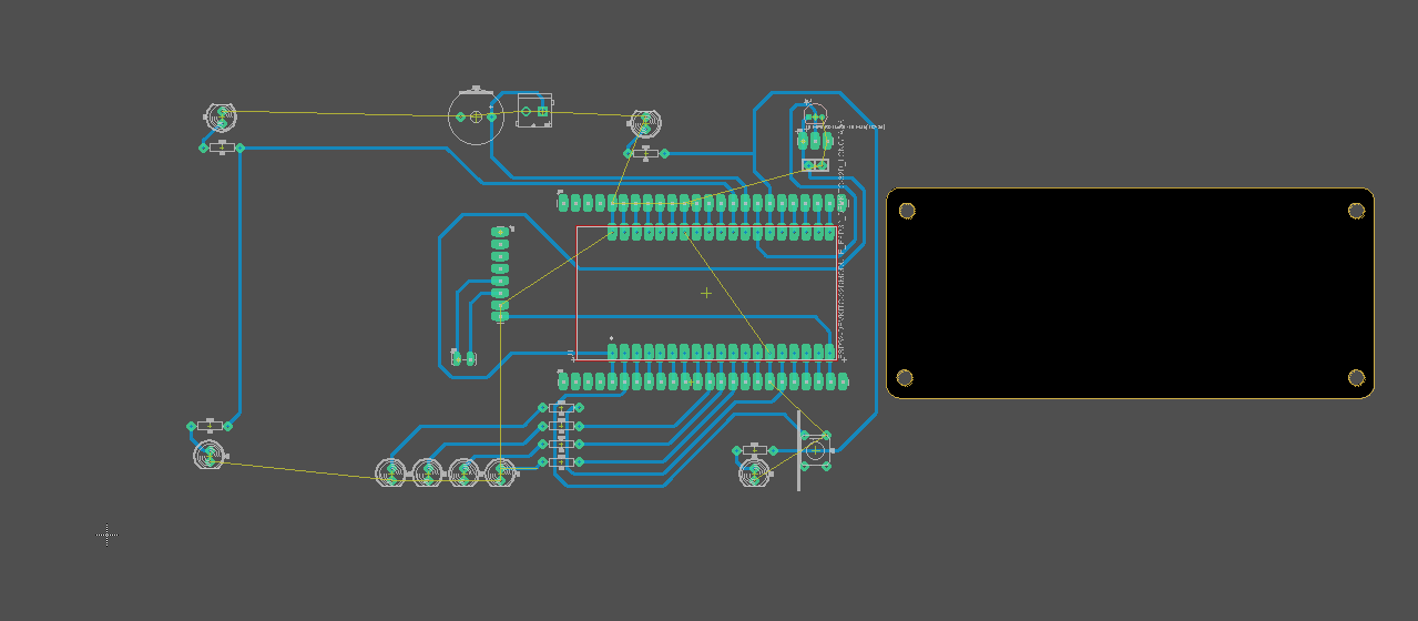
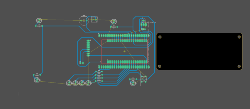
Board routing is done! Needed to do two iterations on it. The first iteration was routed without using the right dimensions on the outline. Oops. With the proper outline imported, everything needed to be placed closer together. Lesson learned: always import the proper outline (or close to it) as the first step. Alright, so the routing was completed fine. It is a 2 layer board with a copper pour on the back of the board. Tolerances for design for fabrication are 20 mils tracewidth, ample spacing at 10+ mils, and using longpads whenever possible. Vias are large like pads, so they can have a wire pass through them during the assembly stage. Next up is milling the board!

by Erin RobotGrrl | Dec 10, 2020 | News, Tech Logs
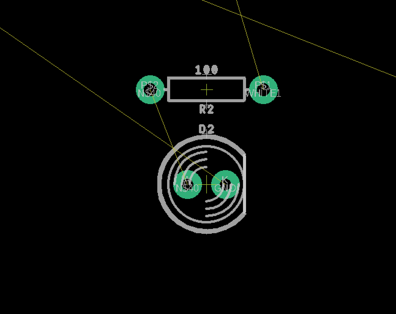
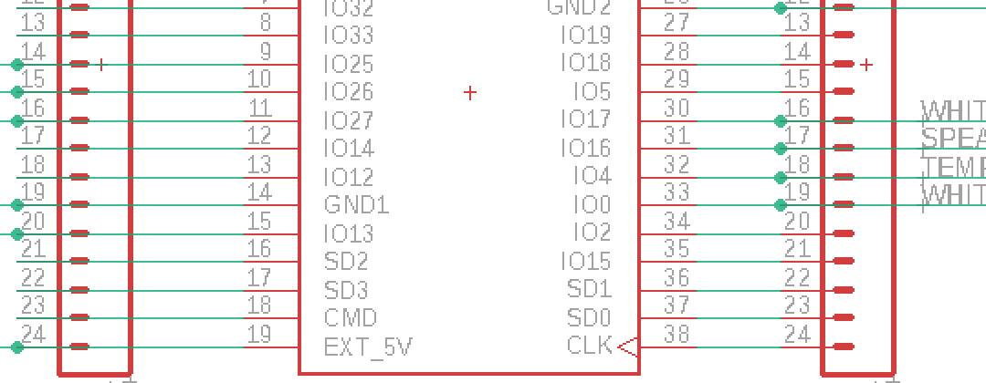
Schematic done for v0.1 of the sensor node! This is the most simplest design possible, with the barebones minimum. An ESP32 breakout, with headers to each side just in case, a reset switch, 6 LEDs, temperature sensor, speaker, and power boost board. All components are through hole at this moment in time. Pretty smooth sailing on this. Next step is to route the circuit board.
by Erin RobotGrrl | Dec 8, 2020 | News, Tech Logs
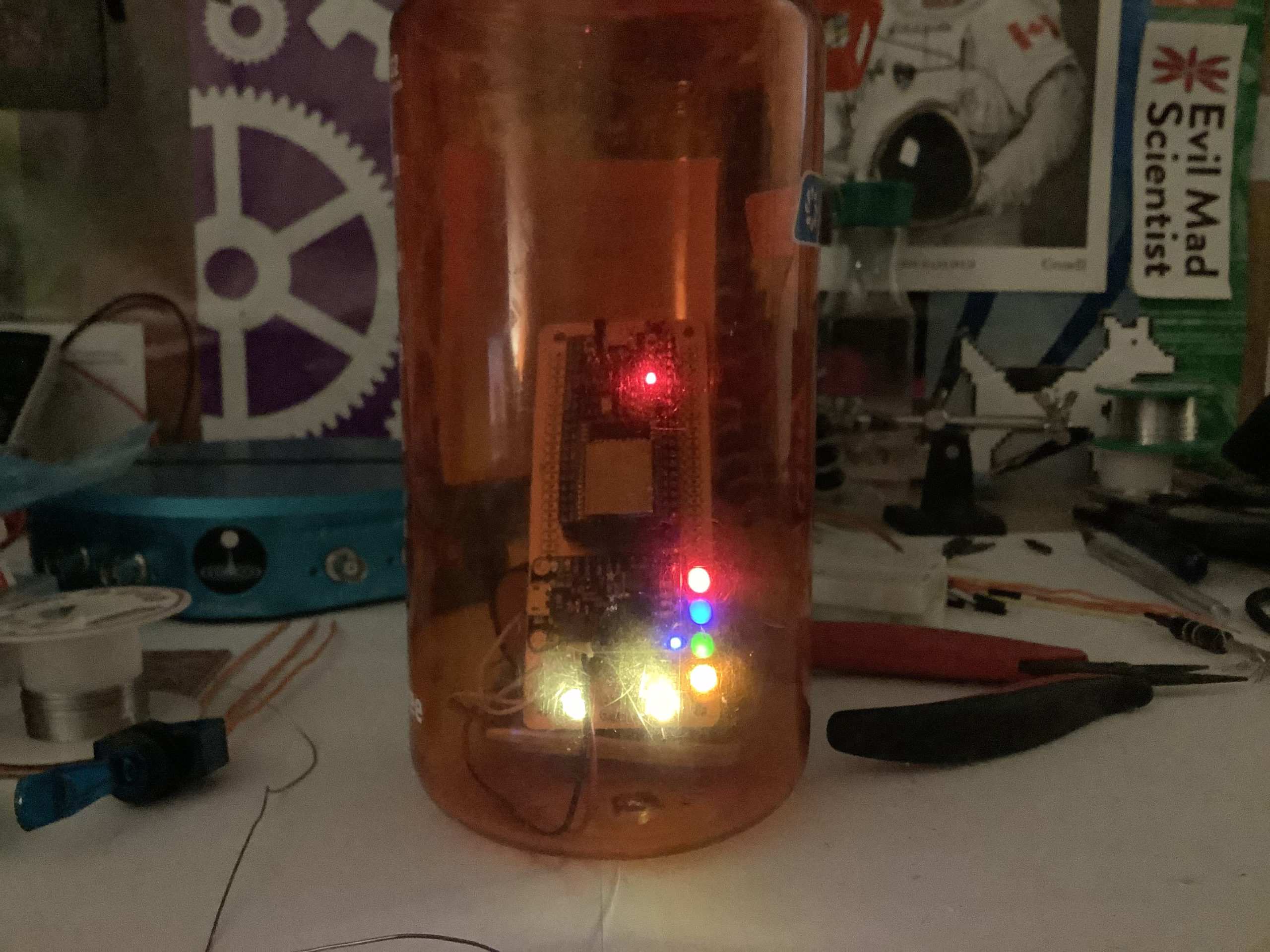
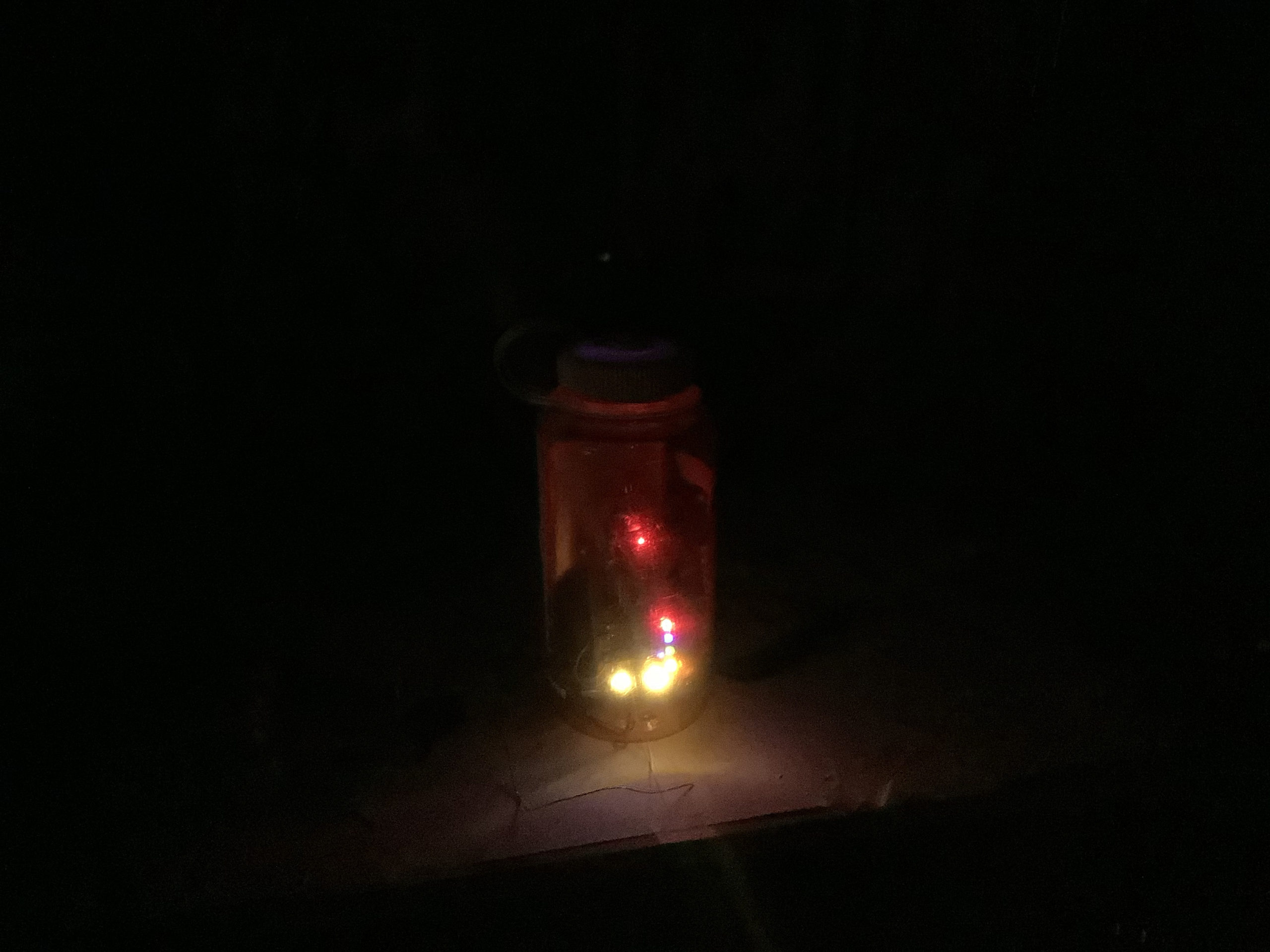
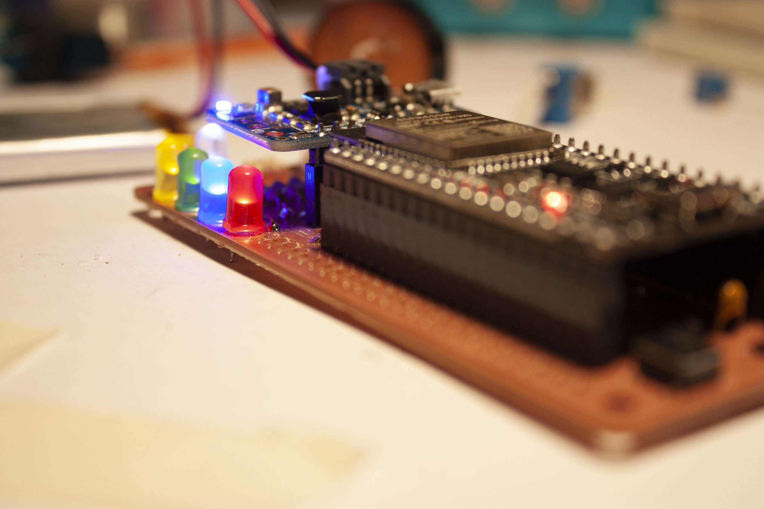
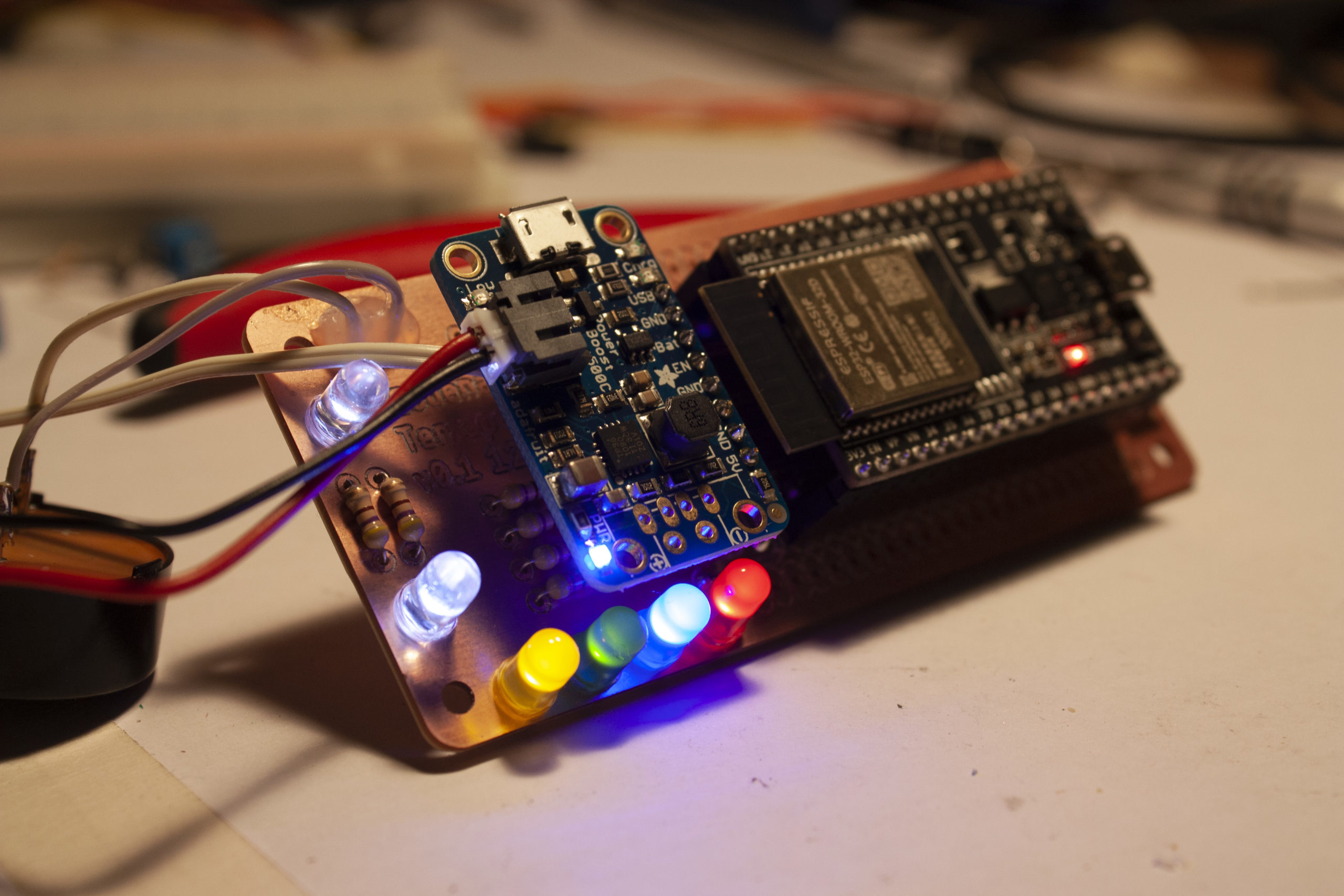
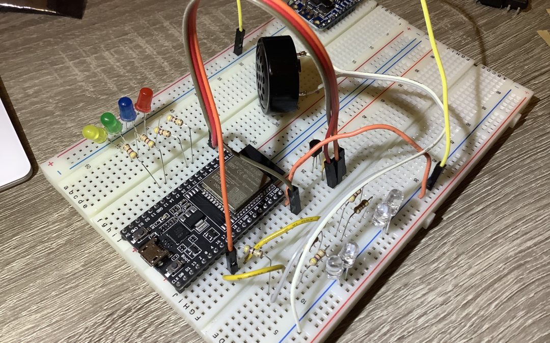
Determined the pins and wired them to the ESP32. Checked the recommended schematic for the temperature sensor, added a 0.1uF cap. There will be 4x white LEDs (2 individually controlled), and 1x red, blue, green, yellow. The purpose of each of these will be determined later when writing the code that connects with MQTT. The white LEDs illuminate an orange Nalgene quite nicely. Found a tone library for the speaker that works with the ESP32. Why use a breadboard for this and not jump right away to circuit board layout? Have run in to situations with the ESP32 where some pins behave differently than originally thought (for example, some pins are output only). Just verifying this works, then can make a pcb. Next step is to write the test code, then schematic capture and board layout. Yay, electronics!

by Erin RobotGrrl | Feb 10, 2020 | News, Progress Logs
One of the tasks on the giant todo list was to fix the Super Bright Lights board. One of its traces is touching a pad, which is an error. It should be a quick thing to fix.
These boards were made in a program called pcb, a part of a suite of tools known as gEDA. It is not a very well known electronics design tool. There is a new fork of pcb called pcb-rnd. There are a few slight changes. Installing pcb-rnd on Mac is straight forward. Installing the other tools in gEDA is not. Specifically, we were looking to install gschem, the schematic editor. We tried brew, fink, but nothing was really working (broken dependencies).
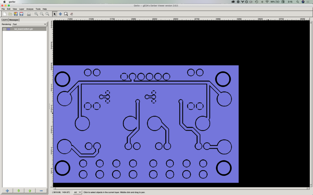
Opening the board in gerbv, we can spot that the error does exist in the file, too. (That’s good news)
After some time re-orientating and remembering how to use pcb, here is the fix in pcb-rnd:
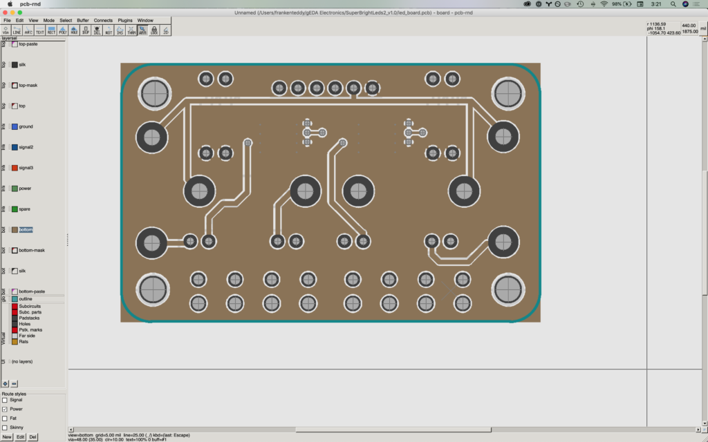
Then flip the board just to check nothing else moved:
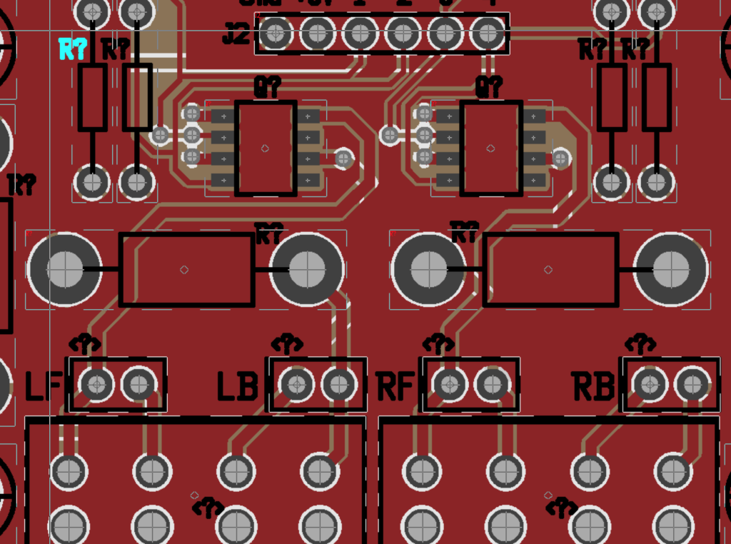
Hey wait a second, there are question marks all over the board! The reference designators are all wiped out. Maybe something happened with the netlist, or some sort of properties file. We couldn’t figure out or remember how to edit the refdes in the new pcb-rnd. We can’t exactly send this board out knowing that there will be question marks printed all over it…
Here’s the errors that were given, justifying the new question marks on the board:
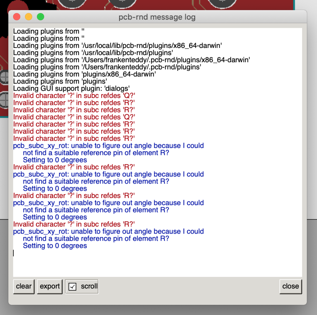
Anyway, we have an old version of pcb on one of our older computers, and we can make the fix using that. However, going forward, it will be wise if we switch from gEDA to Eagle or KiCAD, since the support for gEDA is very minimal at this point in time.