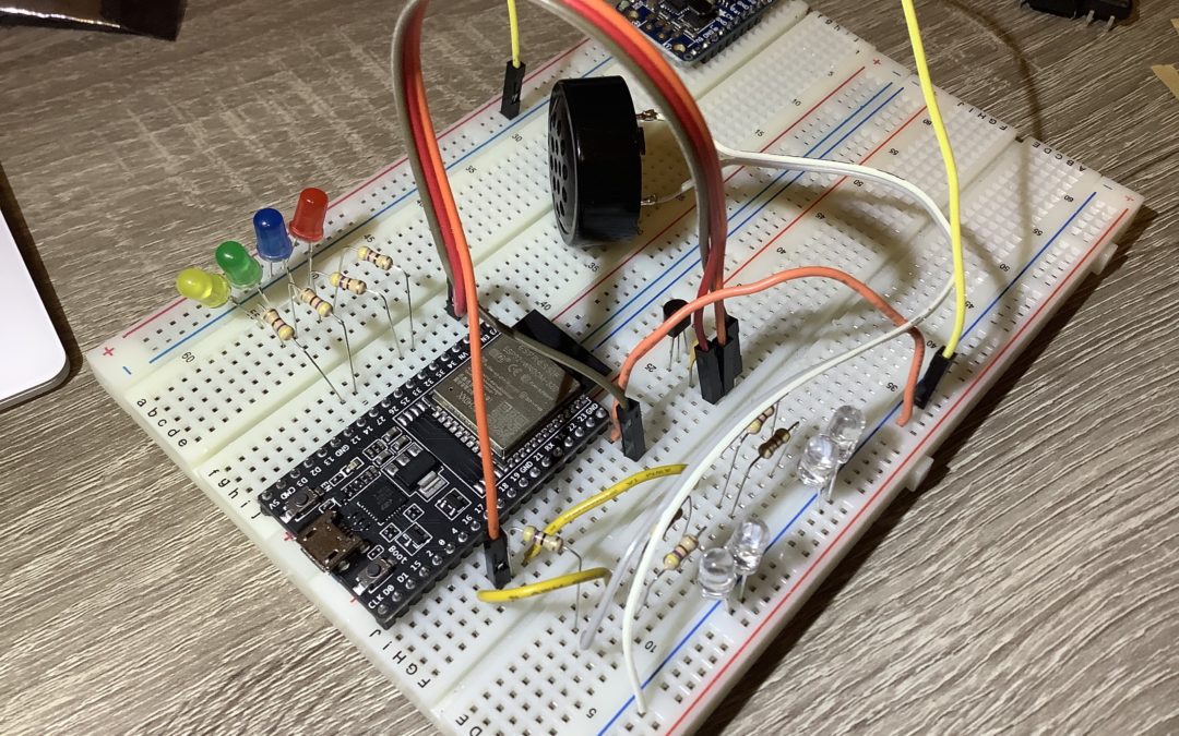
Tech Log #030: Wiring the ESP32 test device
Determined the pins and wired them to the ESP32. Checked the recommended schematic for the temperature sensor, added a 0.1uF cap. There will be 4x white LEDs (2 individually controlled), and 1x red, blue, green, yellow. The purpose of each of these will be determined later when writing the code that connects with MQTT. The white LEDs illuminate an orange Nalgene quite nicely. Found a tone library for the speaker that works with the ESP32. Why use a breadboard for this and not jump right away to circuit board layout? Have run in to situations with the ESP32 where some pins behave differently than originally thought (for example, some pins are output only). Just verifying this works, then can make a pcb. Next step is to write the test code, then schematic capture and board layout. Yay, electronics!